Network usage collection system

Active Publication Date: 2009-03-26
VERIZON PATENT & LICENSING INC
View PDF5 Cites 8 Cited by
  • Summary
  • Abstract
  • Description
  • Claims
  • Application Information

AI Technical Summary

Problems solved by technology

As a result, a vast amount of traffic traverses a network, such as the Internet, on a daily basis.

Method used


Image

  • Network usage collection system
  • Network usage collection system
  • Network usage collection system

Examples


Embodiment Construction

[0017]The following detailed description of exemplary embodiments refers to the accompanying drawings. The same reference numbers in different drawings may identify the same or similar elements. Also, the following detailed description does not limit the invention.

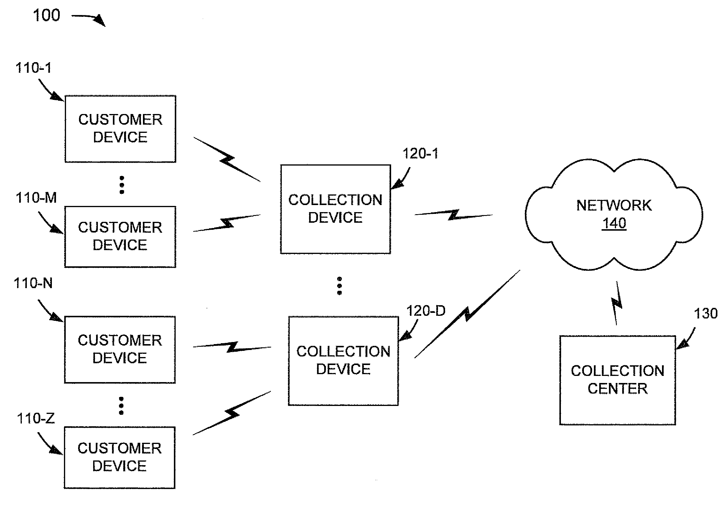
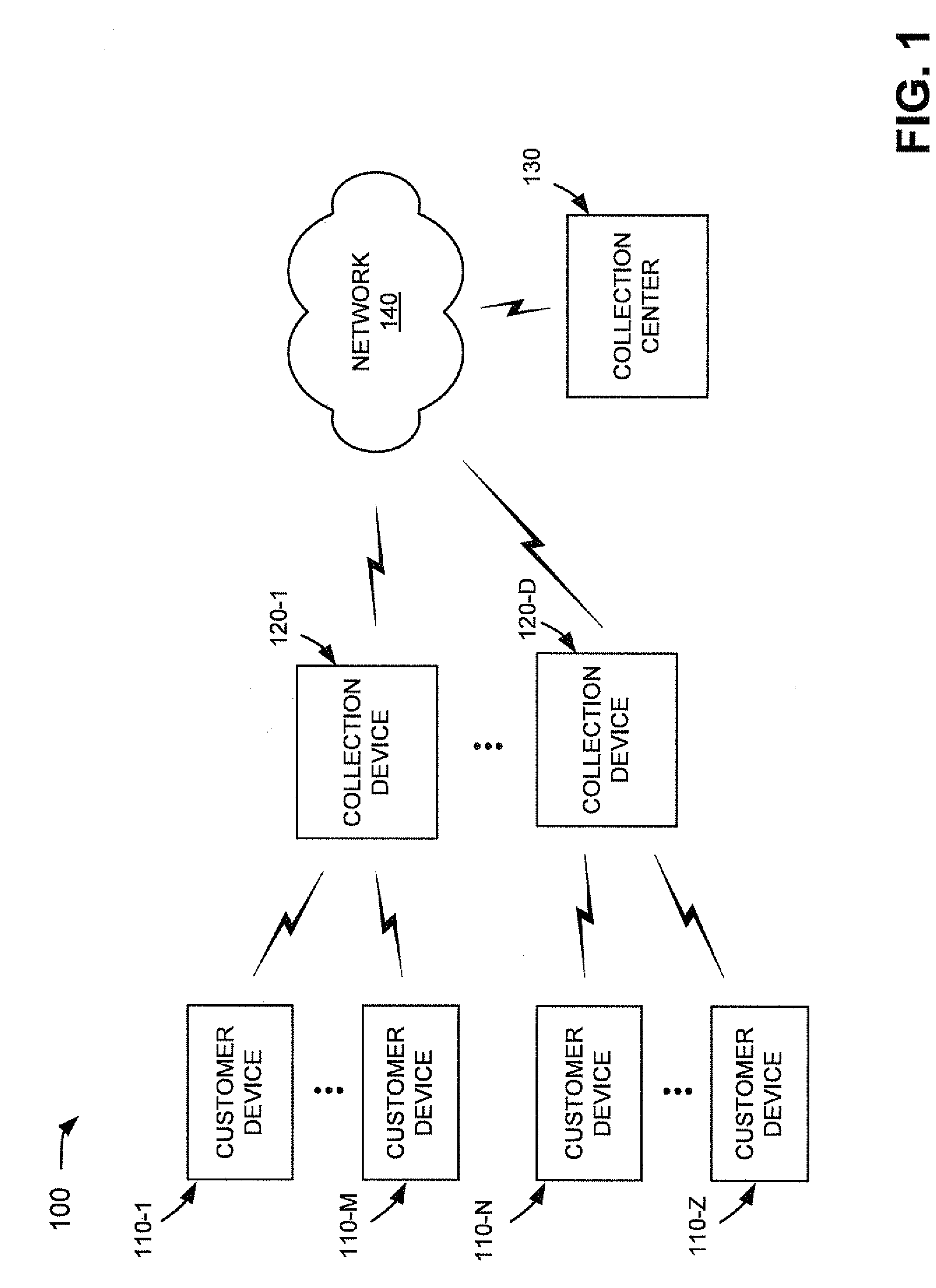
[0018]FIG. 1 is an exemplary network in which systems and methods, consistent with exemplary embodiments, may be implemented. As illustrated, network 100 may include a group of customer devices 110-1 through 110-Z, where M, N, and Z are integers greater than 1 (referred to collectively as “customer devices 110”), a group of collection devices 120-1 through 120-D (referred to collectively as “collection devices 120”), a collection center 130, and a network 140. The number of customer devices 110, collection devices 120, collection centers 130, and networks 140 illustrated in FIG. 1 is provided for simplicity. In practice, there may be more or fewer customer devices 110, collection devices 120, collection centers 130, and / or...


PUM


Abstract

A system includes a first database to associate a sub-interface identifier with customer information, a second database to store a history of customer usage records, and a first device. The first device may receive information from a routing device, where the information includes the sub-interface identifier for a sub-interface of the routing device and information identifying an amount of network traffic received at or transmitted from the sub-interface over a time period, use the sub-interface identifier to obtain the associated customer information from the first database, associate the customer information with the information identifying an amount of network traffic received at or transmitted from the sub-interface over a time period to create a new customer usage record, and store the new customer usage record in the second database.

Description

BACKGROUND INFORMATION[0001]Networks, such as the Internet, have become an increasingly important part of our everyday lives. Millions of people now access the Internet on a daily basis to, for example, shop for goods and services, obtain information of interest (e.g., movie listings, news, etc.), access desired files (e.g., word processing documents, movie files, music files, etc.), and communicate with friends, family, and co-workers (e.g., via e-mail or instant messaging). As a result, a vast amount of traffic traverses a network, such as the Internet, on a daily basis.BRIEF DESCRIPTION OF THE DRAWINGS[0002]FIG. 1 is an exemplary network in which systems and methods, consistent with exemplary embodiments, may be implemented;[0003]FIG. 2 is an exemplary block diagram of the collection device of FIG. 1;[0004]FIG. 3 is an exemplary functional diagram of a portion of the collection device of FIG. 1;[0005]FIG. 4 is an exemplary block diagram of the collection center of FIG. 1;[0006]FI...

Claims


Application Information

Patent Timeline
IPC IPC(8): G06F15/00G06F17/30
CPCG06Q30/04H04L41/5067H04L67/327H04L43/0882H04L67/306H04L43/065H04L67/63
Inventor SINGH, DIGVIJAYKRZANOWSKI, ROMANBEST, GREGORY DALEJHAVERI, MUSTANSIR M.
Owner VERIZON PATENT & LICENSING INC
Why Eureka
Try Eureka