Method for generating optimized constraint systems for retimable digital designs

a technology constraints, applied in the direction of instruments, pulse techniques, computations using denominational number representations, etc., can solve the problems of synthesis not being able to change the population of retimable digital designs, the overall performance and cost of the design, and the affecting of area, power and other cost functions, etc., to achieve the effect of minimizing hardware costs

Active Publication Date: 2009-03-26
CADENCE DESIGN SYST INC
View PDF12 Cites 9 Cited by
  • Summary
  • Abstract
  • Description
  • Claims
  • Application Information

AI Technical Summary

Benefits of technology

[0035]The invention provides a method for generating timing constraint systems, where the constrained object is a digital circuit. The constraints are generated for the use of a digital logic optimization (synthesis) tool. The synthesis tool is used to optimize the circuit, under the applied constraints, so that the circuit exhibits certain desirable timing properties, while at the same time minimizing hardware cost and various other properties.
[0036]The particular class of timing constraints generated by the described method is useful when the circuit is to be retimed after optimization. Typically, the joint use of the described method and retiming results in improvements in the overall cost / performance tradeoff curve of the design.

Problems solved by technology

Furthermore, area, power, and other cost functions are also affected by these tradeoffs.
These decisions have a profound effect on the overall performance and cost of the design.
Also, once HDL analysis or retiming has come up with a flip-flop population, logic synthesis cannot change that population.
Thus, it is easy to construct examples of circuits where a poor choice of the initial flip-flop population can only be remedied with difficulty if at all.
Note however that it is seldom easy to construct a well-chosen constraint set and flip-flop population because the exact positioning of the flip-flops, the delays of the gates, and the clocking constraints collectively determine the slack of the gates and hence the retiming solution.

Method used


Image

  • Method for generating optimized constraint systems for retimable digital designs
  • Method for generating optimized constraint systems for retimable digital designs
  • Method for generating optimized constraint systems for retimable digital designs

Examples


embodiment

PREFERRED EMBODIMENT

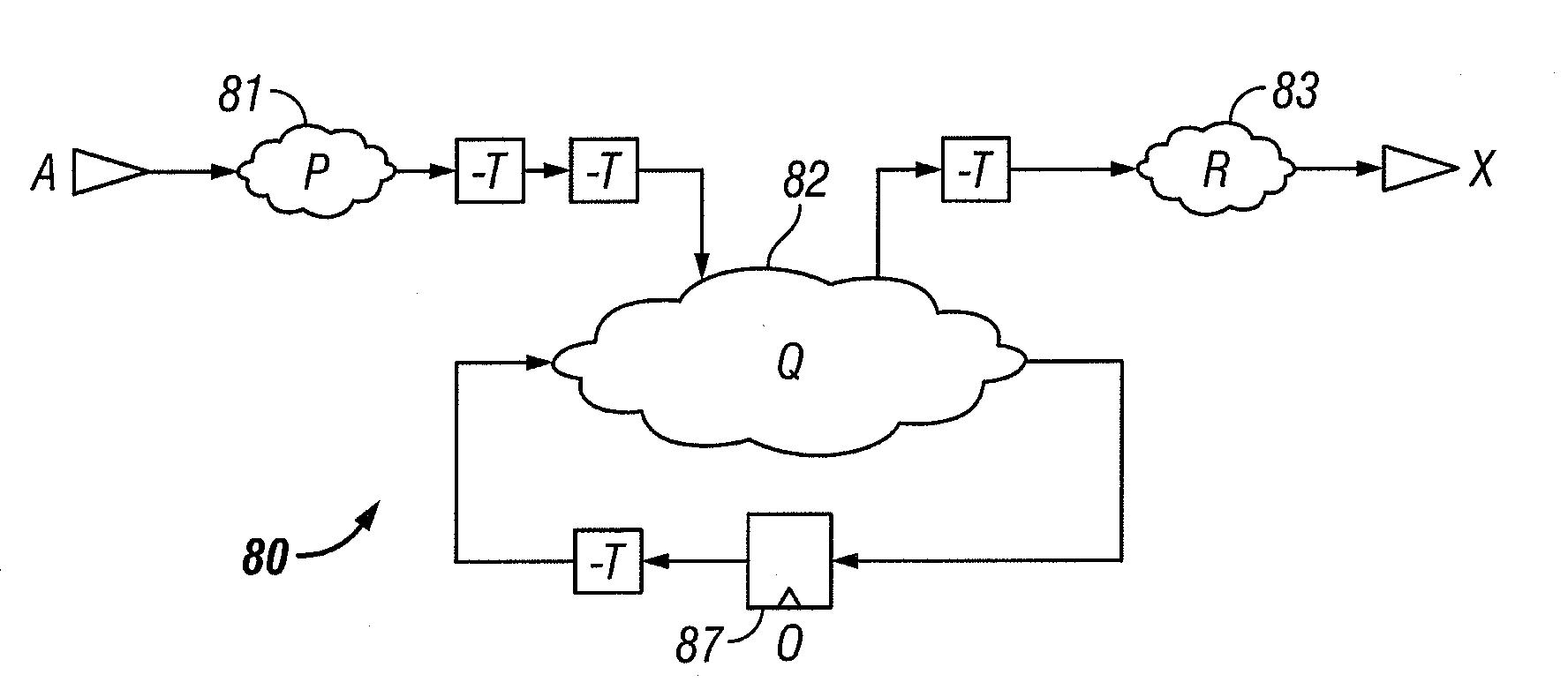
[0058]The constraining method herein described is useful in the context of a (digital) logic synthesis system.

[0059]The method for generating timing constraints consists of the following steps. Each step is described in greater detail below:[0060]1. The circuit is described using a standard HDL. The descriptions should follow certain style and subset guidelines. These guidelines, and the general practice of describing circuits in HDL texts, are well known to practitioners of the art.[0061]2. A circuit is constructed from the HDL description. This circuit consists of gates and flip-flops, with other features (such as hierarchy) that are irrelevant for the purposes of this invention. This process is also well-known.[0062]3. The flip-flops of the circuit are replaced with negative delay elements. These negative-time elements are implemented by buffers having a delay of approximately −T, where T is a delay equal to the flip-flop's clock period less a typical flip-flo...


PUM


Abstract

A method for generating timing constraint systems, where the constrained object is a digital circuit, is provided, where the constraints are generated for the use of a digital logic optimization (synthesis) tool. The synthesis tool is used to optimize the circuit, under the applied constraints, so that the circuit exhibits certain desirable timing properties, while at the same time minimizing hardware cost and various other properties. The particular class of timing constraints generated by the disclosed invention is useful when the circuit is to be retimed after optimization. Typically, the joint use of the described invention and retiming results in improvements in the overall cost / performance tradeoff curve of the design. The invention comprises a method that comprises the following steps: (1) the flip-flops of the design are replaced with buffers having a negative delay whose magnitude is approximately the desired clock cycle time of the design; and (2) cycles in the design are broken using flip-flops having an infinite or quasi-infinite clock frequency. Following optimization by the synthesis tool, the temporary changes can be reverted, and retiming performed on the circuit.

Description

CROSS REFERENCE TO RELATED APPLICATIONS[0001]This application is a divisional of the following currently co-pending application, and claims the benefit thereof in accordance with 35 USC 120: U.S. patent application Ser. No. 10 / 665,880 filed Sep. 19, 2003 and entitled “A METHOD FOR GENERATING OPTIMIZED CONSTRAINT SYSTEMS FOR RETIMABLE DIGITAL DESIGNS.” The entirety of the foregoing application is hereby incorporated by reference.BACKGROUND OF THE INVENTION[0002]1. Technical Field[0003]The invention relates to a method for generating optimized timing constraint systems for retimable digital designs.[0004]2. Description of the Prior Art[0005]The following is a description of a generic logic synthesis system, with descriptive emphasis being given to those aspects of the system that are most relevant to the invention described herein. FIG. 1 shows the flow through a generic logic synthesis system 11 that features retiming, and that produces a netlist 19 expressing an optimized design. Th...

Claims


Application Information

Patent Timeline
Patent Type & Authority Applications(United States)
IPC IPC(8): G06F17/50G06F7/38G06F
CPCG06F17/505G06F30/327
Inventor GIDON, ALEXANDERKNAPP, DAVID
Owner CADENCE DESIGN SYST INC
Why Eureka
Try Eureka