Stator core of electric rotating machine and method of manufacturing the core

a technology of electric rotating machines and stator cores, which is applied in the manufacture of stator/rotor bodies, dynamo-electric components, and the shape/form/construction of magnetic circuits, etc. it can solve the problems of undesirable lowering of the insulation performance of the stator coil covered with an insulation film, the inability to reliably fix the stator core, and the lack of uniformity in the magnetic attraction force. achieve the effect of reliably supplying a rated electric power or rated

Inactive Publication Date: 2009-04-02
DENSO CORP
View PDF6 Cites 13 Cited by
  • Summary
  • Abstract
  • Description
  • Claims
  • Application Information

AI Technical Summary

Benefits of technology

[0028]Accordingly, the stator core can be manufactured according to this method such that the core is reliably fixed in the machine while maintaining a sufficient fixing force against vibrations of the machine. That is, the machine with this core can reliably output a rated electric power or a rated rotational force for a long time.
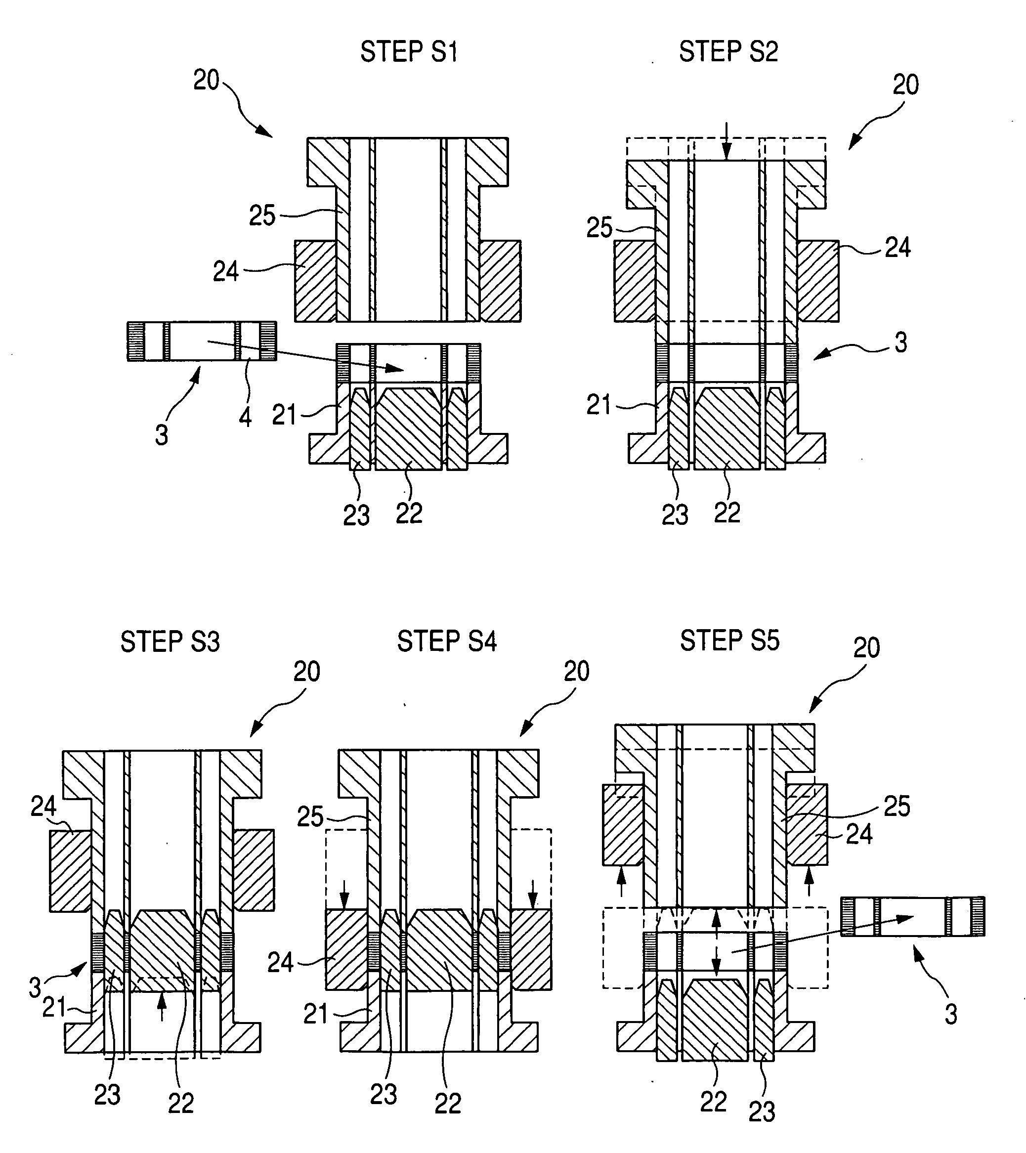
[0029]Further, in this method, the process for forming the steel plate with the teeth, the process for winding the steel plate into the steel sheets and the process for performing the ironing for the steel sheets are performed in the same manner as in the prior art to manufacture a stator core. Accordingly, the stator core can be easily and rapidly manufactured from the steel plate without adding any process performed by using a new processing device.

Problems solved by technology

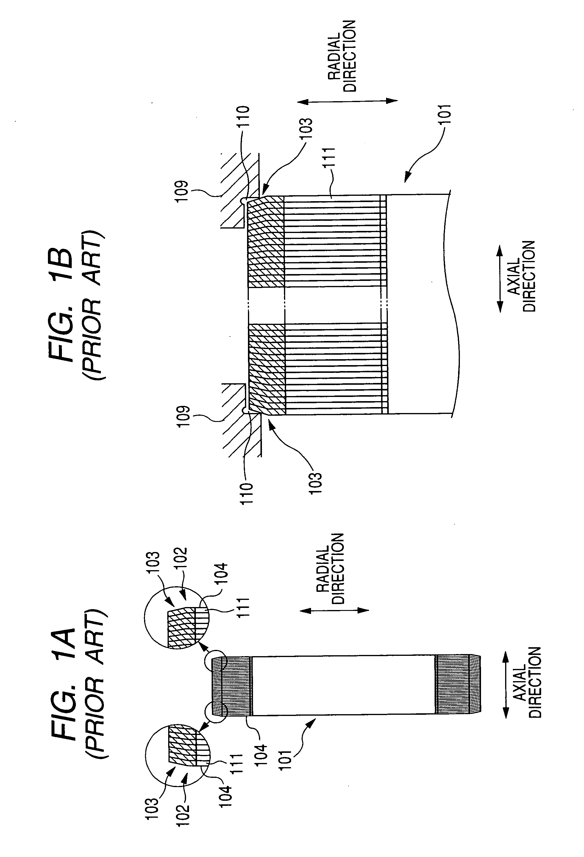
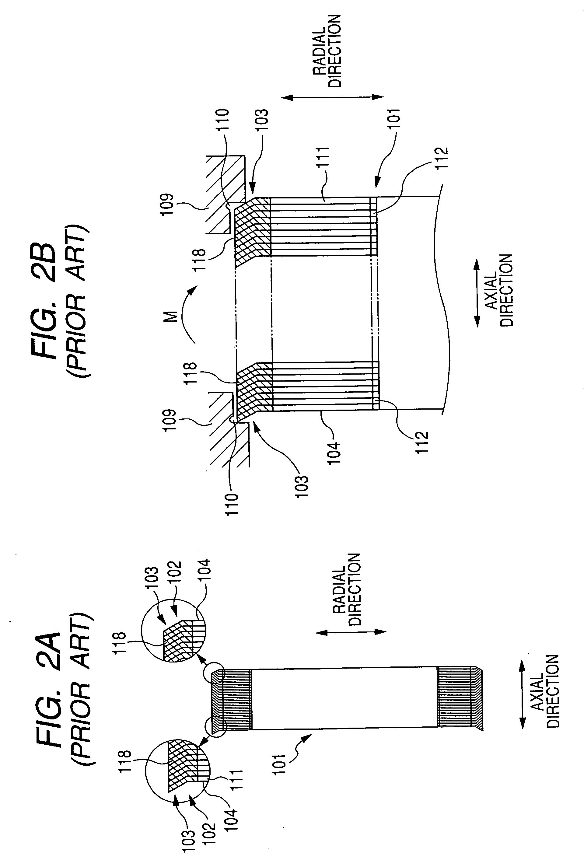
However, it is difficult to reliably fix the stator core 101 to the frame 109.
Further, the magnetic attraction force acting between the stator and the rotor lacks uniformity along the circumferential direction, so that noise caused by the lack of uniformity in the magnetic attraction force is undesirably increased.
In this case, the stator coil inserted into the slots 104 of the core 101 is deformed or damaged, so that the insulation performance of the stator coil covered with an insulation film is undesirably lowered.
However, it is troublesome to cut the end surfaces.
For example, a cutting machine and a cutting tool are required, and it takes a long time to cut the end surfaces.
Therefore, the manufacturing cost of the machine is undesirably increased.

Method used


Image

  • Stator core of electric rotating machine and method of manufacturing the core
  • Stator core of electric rotating machine and method of manufacturing the core
  • Stator core of electric rotating machine and method of manufacturing the core

Examples


embodiment 1

[0050]FIG. 3 is a side view, partially in cross-section, of an upper half portion of an alternator with a stator core according to first and second embodiments.

[0051]As shown in FIG. 3, an alternator 1 representing an electric rotating machine is, for example, mounted in a vehicle. The alternator 1 has a cylindrical stator 2, a columnar rotor 7 disposed in a center hole of the stator 2, a frame 9 covering the stator 2 and the rotor 7, and a plurality of through bolts 8 fastening the stator 2 to the frame 9. The stator 2 has a cylindrical stator core 3 and a plurality of stator coils 10 wound on the core 3. The rotor 7 acts as an armature. The stator 2 acts as a field.

[0052]The stator core 3 is placed in an opening between side walls of the frame 9 and is fastened to the frame 9 by the through bolts 8 penetrating through the frame 9. Each side wall of the frame 9 extends to be perpendicular to the axial direction (or center axis) of the core 3.

[0053]With this structure of the alterna...

embodiment 2

[0097]In the first embodiment, each steel sheet 11 extends straight in the radial direction. However, the boundary portion 17 of each steel sheet 11 may be inclined toward the axial direction on condition that the group of divided end portions 15 of each steel sheet 11 extends in a plane perpendicular to the radial direction to be parallel to the group of teeth 12 of the sheet 11.

[0098]FIG. 10A is a plan view of a portion of the steel plate 13 according to the second embodiment, while FIG. 10B is a sectional view taken substantially along line D-D of FIG. 10A. FIG. 11A is a plan view of a portion of the laminated core 3 obtained by winding the plate 13 shown in FIG. 10A, while FIG. 11B is a sectional view taken substantially along line E-E of FIG. 11A. FIG. 12 is a longitudinal sectional view of the stator core 3 fastened to the frame 9.

[0099]As shown in FIG. 10A and FIG. 10B, after the slits 14 and the depressions 16 are formed in the plate 13, the boundary portion 18 is inclined i...


PUM

PropertyMeasurementUnit
thicknessaaaaaaaaaa
widthaaaaaaaaaa
cylindrical shapeaaaaaaaaaa

Abstract

A stator core of an electric rotating machine has steel sheets formed of a steel plate wound in the cylindrical shape. Each sheet has teeth disposed along the circumferential direction of the core on the inner side of the sheet, divided end portions disposed along the circumferential direction on the outer side of the sheet, slits alternately disposed with the divided end portions along the circumferential direction, and a boundary portion disposed between the group of teeth and the group of divided end portions. The teeth and the divided end portions substantially have the same constant thickness. The boundary portion has a changing thickness decreased toward the outer side.

Description

CROSS-REFERENCE TO RELATED APPLICATION[0001]This application is based upon and claims the benefit of priority of the prior Japanese Patent Application 2007-253518 filed on Sep. 28, 2007, so that the contents of which are incorporated herein by reference.BACKGROUND OF THE INVENTION[0002]1. Field of the Invention[0003]The present invention relates to a stator core of an electric rotating machine which has a plurality of ring-shaped steel sheets obtained from a single steel plate wound in the cylindrical shape. The present invention also relates to a method of manufacturing the core wherein each steel sheet is lengthened in the circumferential direction when the steel plate is wound into the steel sheets.[0004]2. Description of Related Art[0005]As an electric rotating machine generating a rotational force or electric power, a helical stator core has been generally used. To form this stator core, magnetic pole teeth are press-formed on one side of a long steel plate, and the steel plate...

Claims


Application Information

Patent Timeline
Patent Type & Authority Applications(United States)
IPC IPC(8): H02K15/02H02K1/16
CPCH02K15/026Y10T29/49009Y10T29/49002
Inventor TOKIZAWA, TAKASHI
Owner DENSO CORP
Why Eureka
Try Eureka