
Gas phase shifting multistage displacer cryocooler

Inactive Publication Date: 2009-04-02
THE AEROSPACE CORPORATION
View PDF14 Cites 12 Cited by
  • Summary
  • Abstract
  • Description
  • Claims
  • Application Information

AI Technical Summary

Benefits of technology

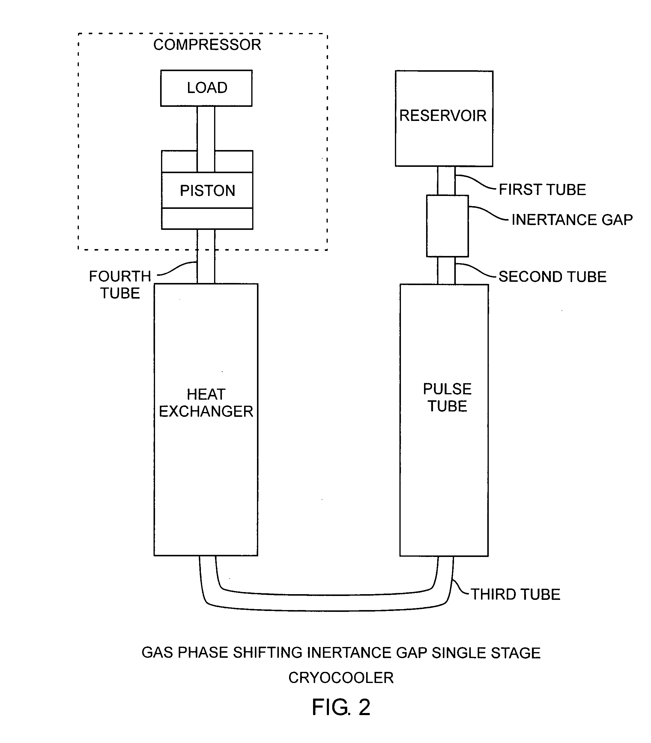
[0015]The invention is directed to gas phase shifting in cryocoolers for improved cooling efficiency. In a first aspect, a valve is disposed between stage volumes in a multistage displacer cryocooler. In a second aspect, inertance gaps are disposed in line of a pulse tube cryocooler. A gas phase shifting means is installed between different volumes of the stages of the cryocooler allowing the cryocooler to operate with wider heat loads and temperature ranges. The gas phase shifting device provides for load shifting between the stages in a multistage mechanical cryocooler. In a displacer cryocooler, the gas phase shifting can be achieved by installing a phase shifting device between the expansion volumes. The gas phase shifting device can be a flow impedance device, for example, a valve, a sharp-edged orifice, or a porous medium in an expander cryocooler. The gas phase shifting device can also be a flow inertia device, for example, an inertance gap in a pulse tube of a cryocooler. The gas phase shifting device phase shift the gas pressure in phase with mass flow at the cold end of the cryocooler for maximum cooling. These and other advantages will become more apparent from the following detailed description of the preferred embodiment.

Problems solved by technology

With a sharp edged orifice, the only variable parameter is the diameter of the orifice, limiting heat exchange control.
Unfortunately, the long tube geometry is also cumbersome, heavy, and bulky.
The long inertance tube does not readily provide the means for optimizing the gas phase shift between the compressor and reservoir for various applications, which requires different cooling capacity.
Additionally, inertance can be increased by increasing the length of tube, but this disadvantageously results in a long and slender tube.
The pulse tube system disadvantageously includes an elongated inertance tube having a length that is longer than a meter in most applications.
The packaging of a long tube presents problems as well as in applications where vibration, such as during a launch, may cause failure of the cooler.
Expander cryocoolers are in general more efficient than pulse tube cryocoolers, however, the displacer cryocoolers are less reliable due to the presence of a moving displacer.
The hybrid design tends to combine the main disadvantage of a expander cryocooler with that of a pulse tube cryocooler.
Multistage coolers are generally used to reach temperatures below 35° K. The shifting of loads between stages is not flexible in a multistage mechanical cryocooler.
Thus, there is disadvantageously a limited range of temperature that each stage can achieve relative to other stages.

Method used


Image

  • Gas phase shifting multistage displacer cryocooler
  • Gas phase shifting multistage displacer cryocooler
  • Gas phase shifting multistage displacer cryocooler

Examples


Embodiment Construction

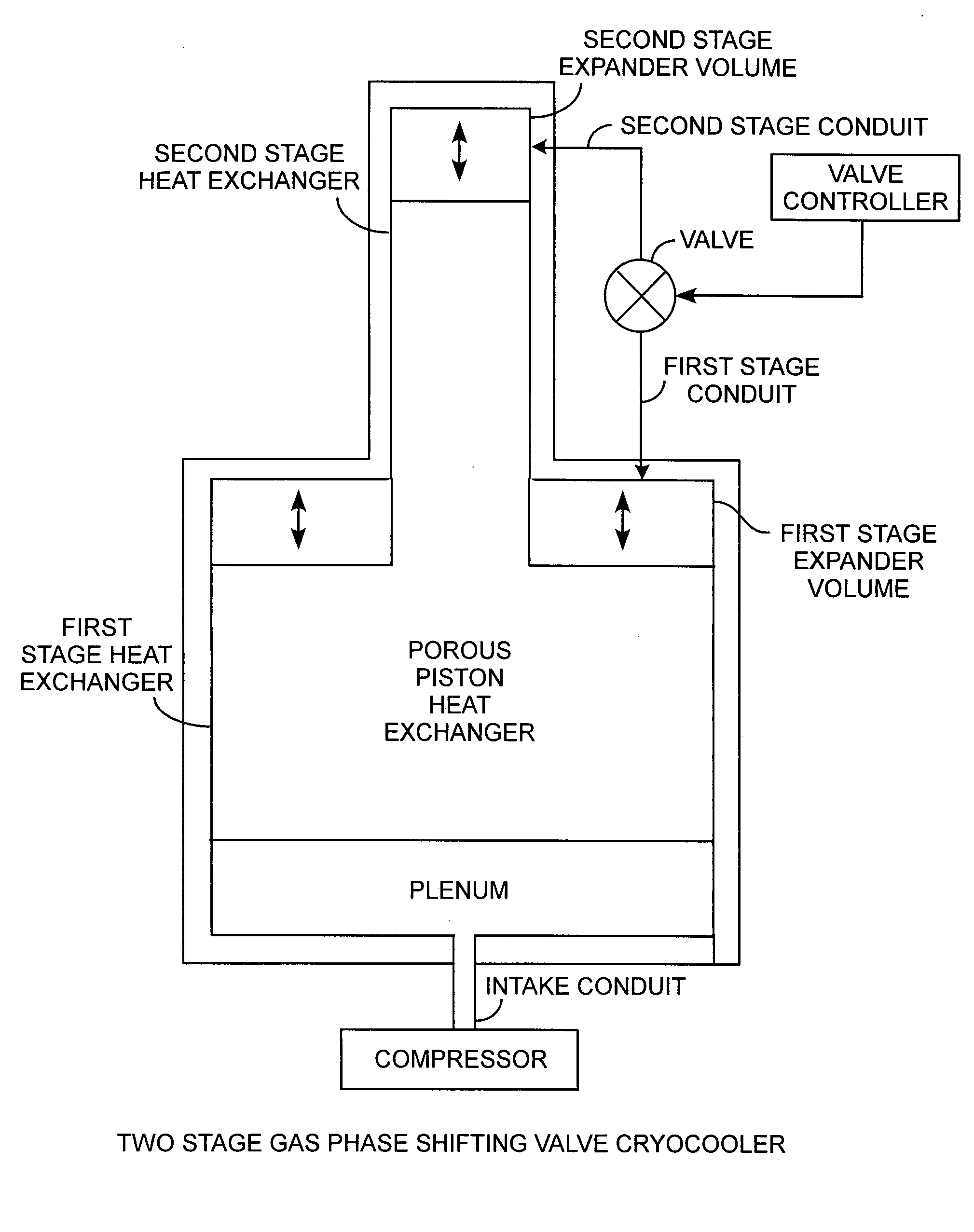
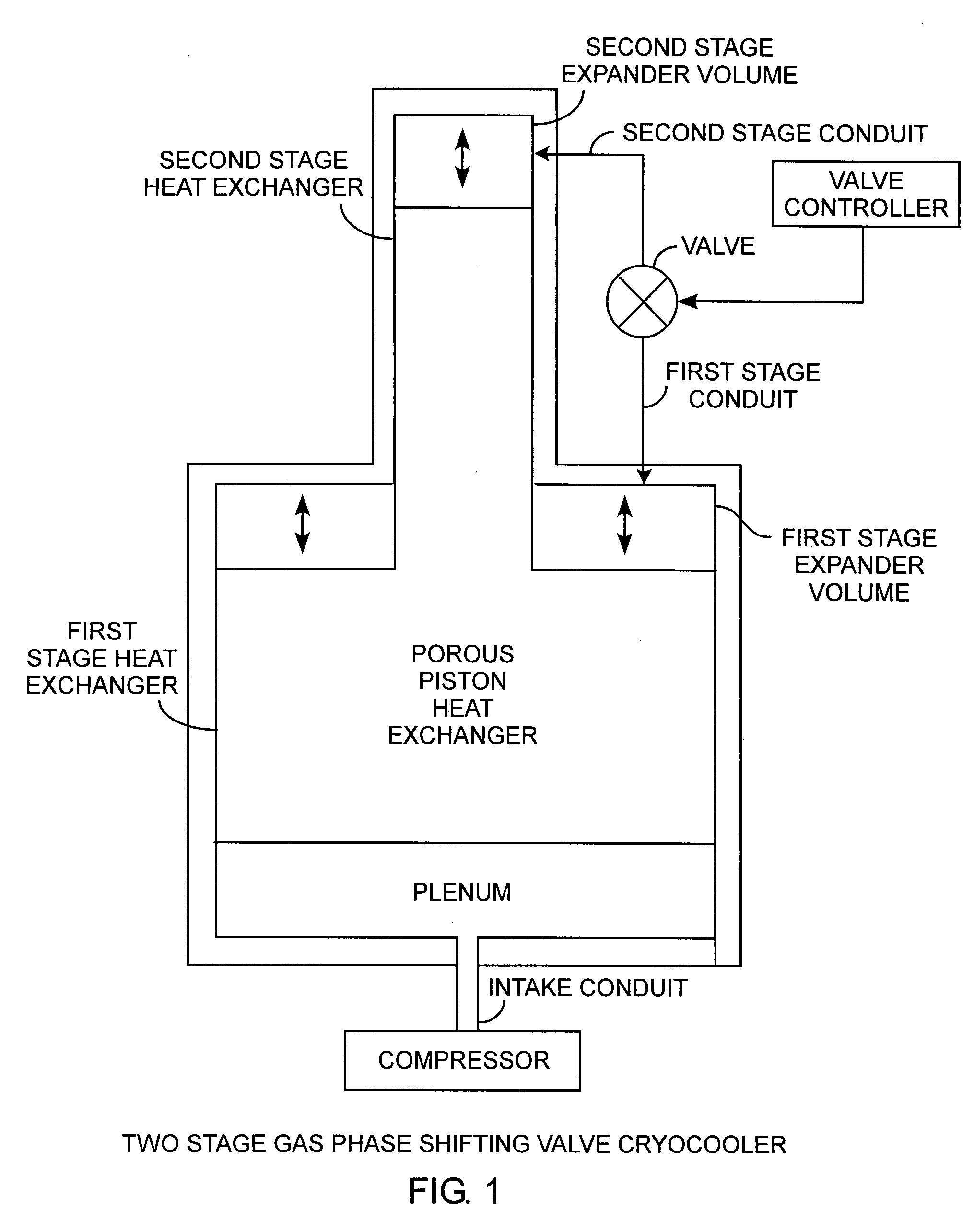
[0022]An embodiment of the invention is described with reference to the figures using reference designations as shown in the figures. Referring to FIG. 1, a two-stage gas phase shifting valve cryocooler is a modified version of a conventional two-stage cooler with a moving porous piston heat exchanger. The porous piston heat exchanger, or simply the regenerator, functions as a heat exchanger. The porous piston is bifurcated for heat exchange into a first stage heat exchanger for exchange heat with a first stage volume and into a second stage heat exchanger for heat exchange with a second stage volume. A compressor provides the pressure and volume work required for cooling, by moving the piston. The compressor injects gas through an intake conduit into an empty volume, known as a plenum. The gas is cooled when passing through the porous heat exchanger. The piston in the cryocooler moves when a parcel of gas is admitted into the plenum through the intake conduit. The parcel of gas the...


PUM


Abstract

A displacer cryocooler including a multistage heat exchanger is modified with a phase shifting device connected between stage volumes for gas phase shifting of gas pressure in the cryocooler for improving the efficiency and temperature range of expander cryocoolers.

Description

REFERENCE TO RELATED APPLICATION[0001]The present application is related to applicant's copending applications entitled Gas Phase Shifting Multistage Displacer Cryocooler, Ser. No. xx / xxx,xxx, filed xx / xx / xx, Controlled and Variable Gas Phase Shifting Cryocooler Ser. No. yyy / yyy,yyy, filed yy / yy / yy, and Gas Phase Shifting Inertance Gap Pulse Tube Cryocooler, Ser. No. zz / zzz,zzz, filed zz / zz / zz, by the same inventors.FIELD OF THE INVENTION[0002]The invention relates to the field of refrigeration systems. More particularly, the invention relates to cryocoolers providing phase shifting of gas pressures using controlled gas phase shifting devices in a multiple stage expander cryocooler and multiple stage pulse tube cryocooler for improved energy transfer and cooling efficiencies.BACKGROUND OF THE INVENTION[0003]Cryocoolers are mechanical machines used for cooling, heating, and thermal transfer. The cryocoolers typically have multiple internal volumes for heating and cooling. Multistage ...

Claims


Application Information

Patent Timeline
IPC IPC(8): F25B7/00F25B9/14
CPCF25B9/14F25B9/145F25B2309/1424F25B2309/1418F25B2309/1408
Inventor YUAN, SIDNEY W.K.CURRAN, DAVID G.T.
Owner THE AEROSPACE CORPORATION
Learn More