Nose mask

a nose mask and anesthesia technology, applied in the field of nose masks, can solve the problems of difficult to apply a sufficient amount of anesthesia to the laboratory animal, and difficult to prevent the anesthesia gas leaked from the nose mask from remaining in the casing

Inactive Publication Date: 2009-04-02
FUJIFILM CORP
View PDF10 Cites 8 Cited by
  • Summary
  • Abstract
  • Description
  • Claims
  • Application Information

AI Technical Summary

Benefits of technology

[0018]In accordance with the nose mask of the present invention, the nose mask comprises the anesthesia tube having an anesthesia supply section which opens to an wall of the anesthesia tube so that the anesthesia is applied to the laboratory animal by inserting the nose of the laboratory animal, and the outer wall which is disposed outside the anesthesia tube to form a space therebetween and the a

Problems solved by technology

Introduction and discharge of the anesthesia gas into and from the nose mask in the casing can result in fear that the anesthesia gas leaked from the nose mask can remain in the casing.
When the anesthesia gas remains in the casing can result in fear that the worker inspires the anesthesia gas when taking out the laboratory animal upon end of the image taking.
In the technic disclosed in PCT Japanese Publication No. 2005-517507, when the flow of the anesthesia gas upon disch

Method used


Image

  • Nose mask
  • Nose mask
  • Nose mask

Examples


Embodiment Construction

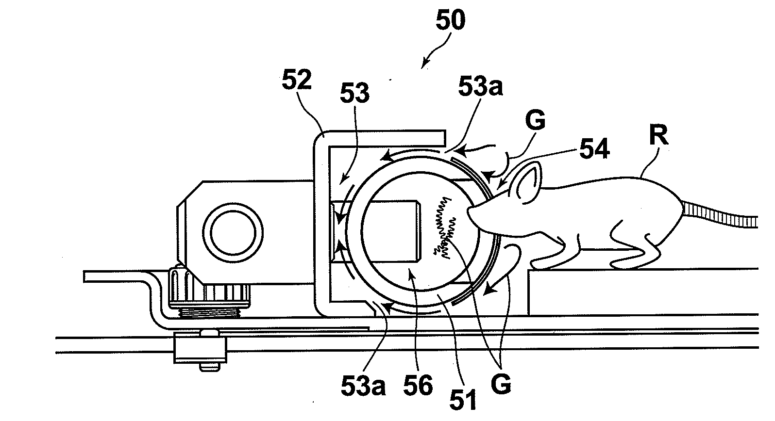
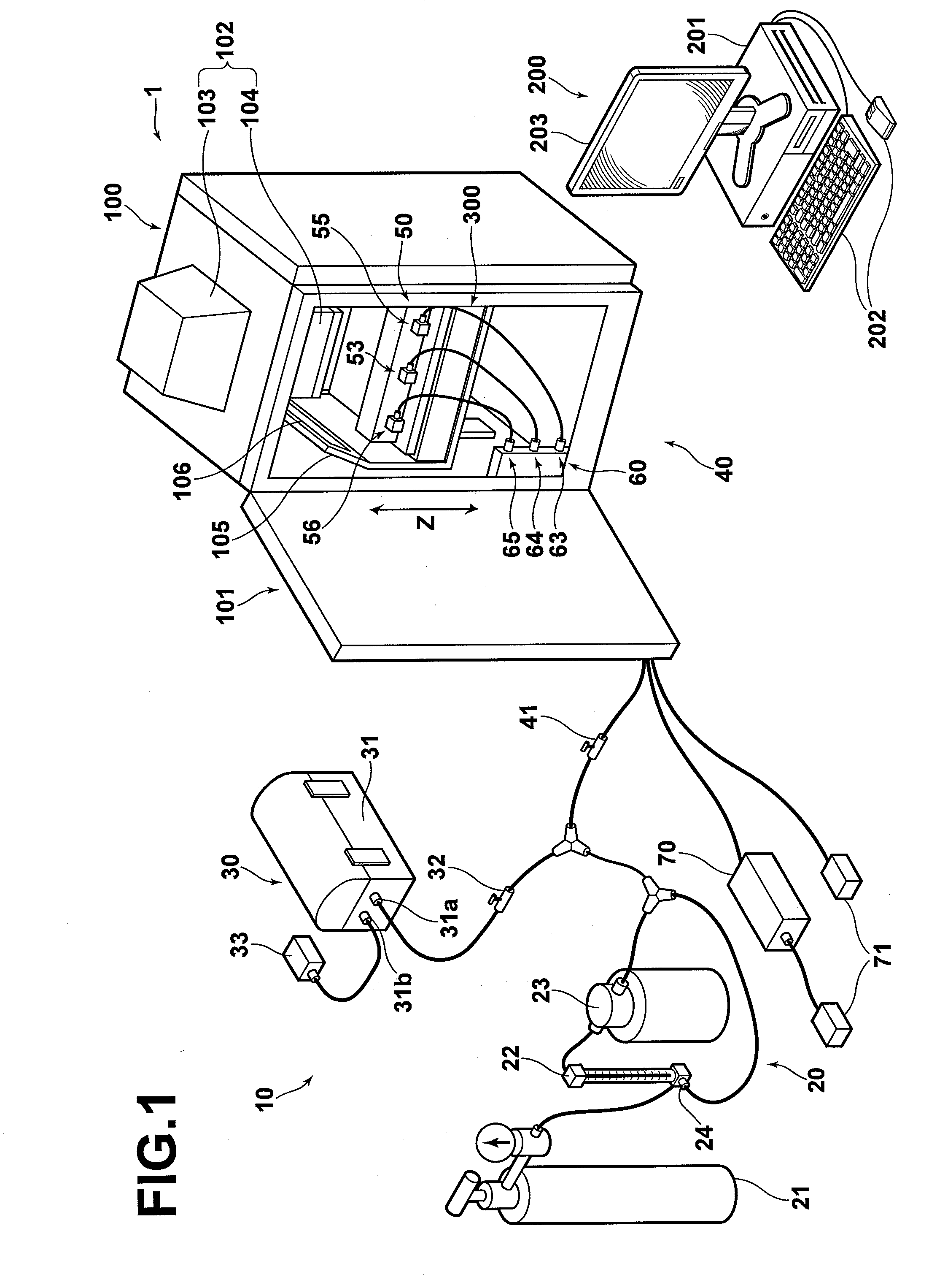
[0035]Embodiments of a nose mask 50 of the present invention will be described with reference to the drawings, hereinbelow. FIG. 1 is a view showing an image taking system 1 employing the nose mask 50 of the present invention. The image taking system 1 of FIG. 1 comprises a casing means 101 for taking an image of fluorescent light or chemiluminescence generated from a laboratory animal R, an image taking means 102, a control means 200, an incubator means 300 and an anesthesia system 10.

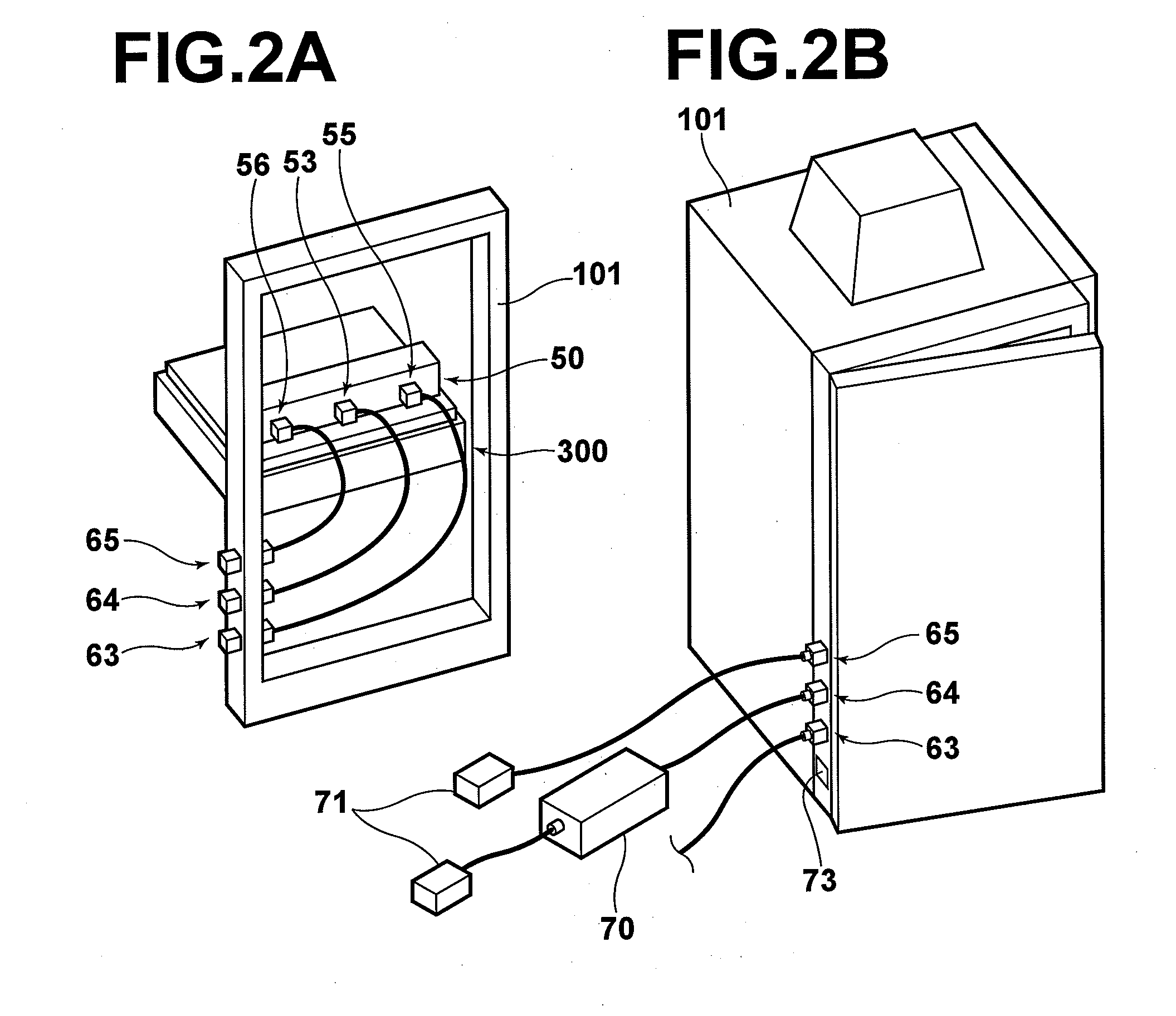
[0036]The casing means 101 has a rectangular hollow portion in which a laboratory animal R is housed. The casing means 101 has a lid which is mounted to the casing means 101 to be opened so that the user can takes in and out the laboratory animal R. The casing means 101 comprises a housing 105 disposed therein and a light source 106 above the housing 105.

[0037]The housing 105 is movable up and down (in the direction of Z in FIG. 1) in the casing means 101 by a drive section (not shown). The light sour...


PUM


Abstract

A nose mask for applying an anesthesia gas to a laboratory animal in a casing means includes an anesthesia tube, an outer wall which is disposed outside the anesthesia tube to form a space therebetween and an anesthesia recovery system having an anesthesia recovery port open to the space. The anesthesia tube includes an anesthesia supply section which opens to an wall of the anesthesia tube so that the anesthesia is applied to the laboratory animal by inserting the nose of the laboratory animal, an anesthesia introducing section for introducing the anesthesia gas to the anesthesia tube, and an anesthesia discharging section for discharging the anesthesia gas from the anesthesia tube.

Description

BACKGROUND OF THE INVENTION[0001]1. Field of the Invention[0002]This invention relates to a nose mask for applying an anesthesia gas to the laboratory animal.[0003]2. Description of the Related Art[0004]Recently, there has been in wide use a method called “in vivo imaging” where an in vivo action in a laboratory animal such as mouse is directly observed as it is alive. For example, after a diseased part such as tumor is created in the laboratory animal, and agents labeled by phosphors and the like is dosed in the laboratory animal through a blood vessel injection, collection or dispersion of the agents with time to and from the diseased part can be observed by projecting an exciting light onto the diseased part.[0005]Further, there exists a method of chemiluminescence where a biological tissue is investigated (gene analysis, disease, aging) or an organic material or a polymer is evaluated using a reaction where light is emitted (chemiluminescence) with the reaction when materials re...

Claims


Application Information

Patent Timeline
IPC IPC(8): A61D7/04
CPCA61D7/04
Inventor ICHIKAWA, SHINICHI
Owner FUJIFILM CORP
Why Eureka
Try Eureka