
Tubal ligation

a technology of ligation and tubule, applied in the field of tissue occlusion systems and methods, can solve the problems of unsatisfactory recovery time and discomfort, unreliable or impermanent blockage, and relatively difficult to achieve successfully

Inactive Publication Date: 2009-04-02
HOLOGIC INC
View PDF71 Cites 40 Cited by
  • Summary
  • Abstract
  • Description
  • Claims
  • Application Information

AI Technical Summary

Benefits of technology

The present invention provides a system and method for applying a clamping structure to the interior of a tubular anatomical structure, such as a blood vessel or an ovary, without the need for general surgery or endoscopic surgery. The system includes an assembly with an anchor, hinge, and surface in opposition to the anchor. The anchor can pivot upon the hinge and move at least a portion of the assembly in a way that allows for easy and reliable ligation. The system can also include a distal grasper element and a proximal grasper element for expanding a portion of a cannula in which the grasper elements are inserted to form a fold in the cannula. The system can provide a solution for minimizing damage to vascular and reproductive tissues, reducing post-surgery discomfort and recovery time, and reducing the risk of infection.

Problems solved by technology

Such methods are less invasive than conventional surgical methods but still have an high risk of infection, require anesthesia, cause tissue damage, and are accompanied by an undesirable recovery time and level of discomfort.
However, either type of plug may separate or dislodge from the wall of the fallopian tube, resulting in unreliable or impermanent blockage.
However, this method is relatively difficult to accomplish successfully and requires skilled personnel and specialized equipment, making it unsuitable for use in certain settings.

Method used


Image

  • Tubal ligation
  • Tubal ligation
  • Tubal ligation

Examples


Embodiment Construction

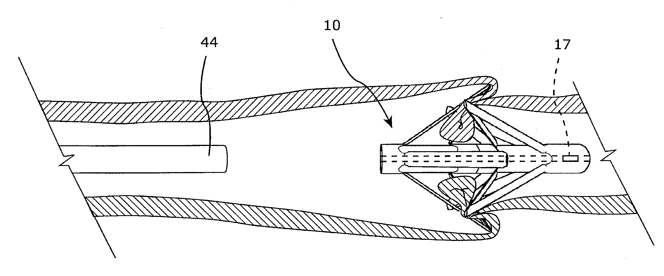
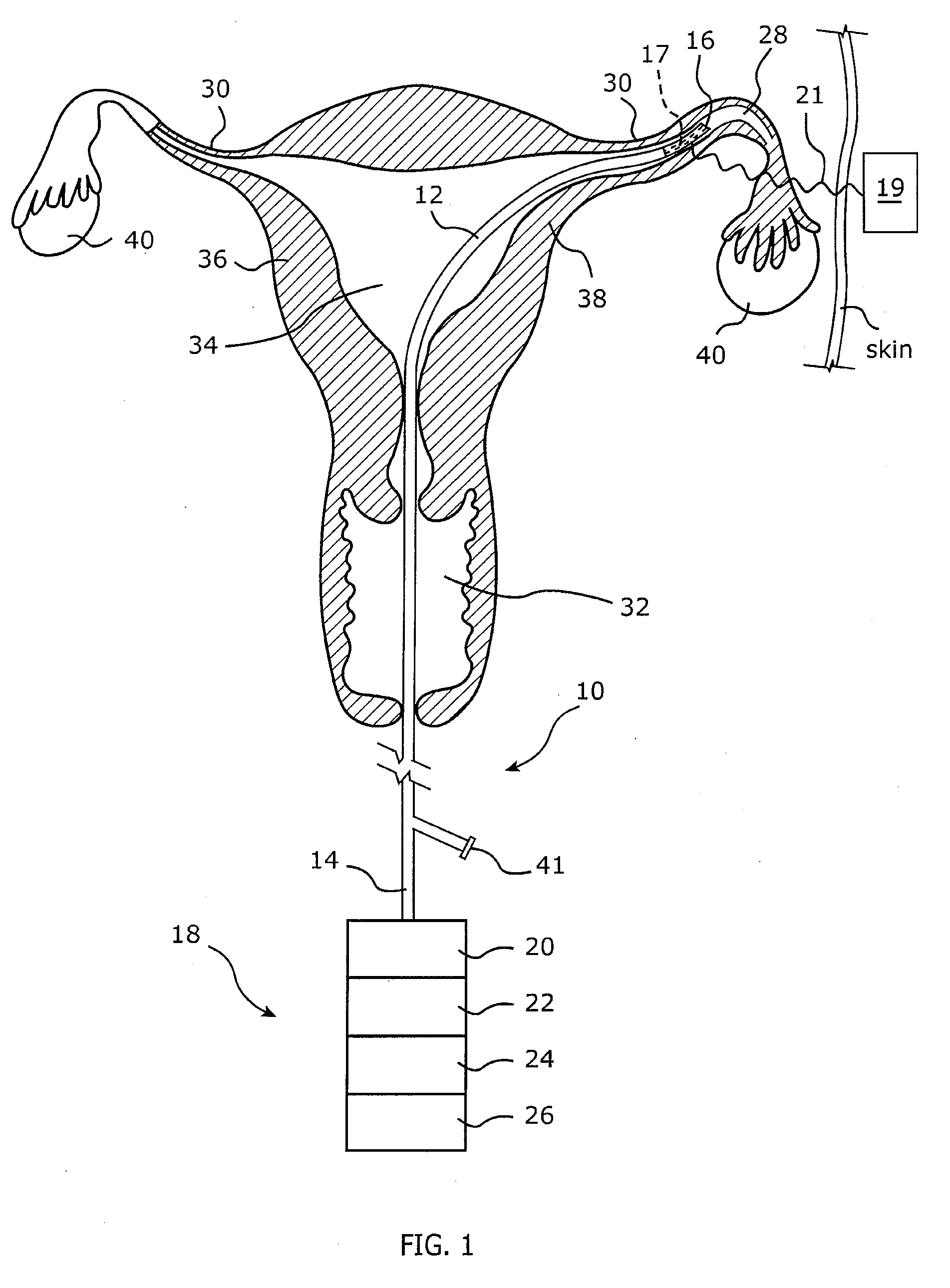
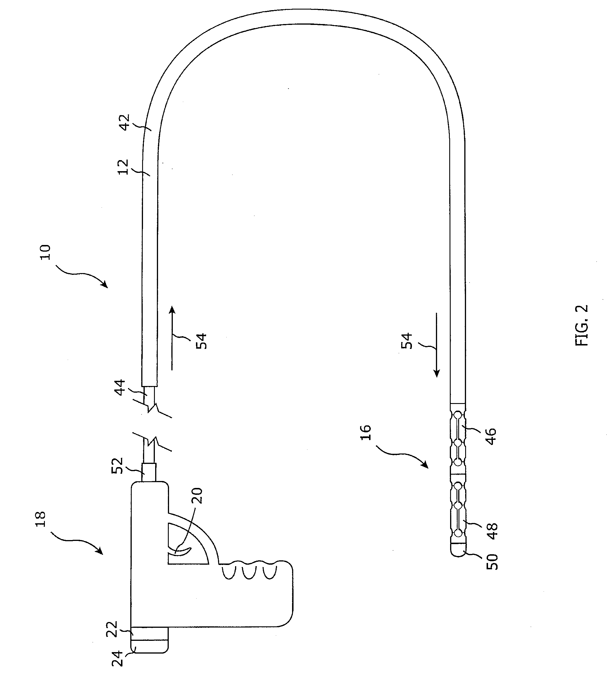
[0039]The presently preferred embodiments of the present invention will be best understood by reference to the drawings, wherein like reference numbers indicate identical or functionally similar elements. It will be readily understood that the components of the present invention, as generally described and illustrated in the figures herein, could be arranged and designed in a wide variety of different configurations. Thus, the following more detailed description, as represented in the figures, is not intended to limit the scope of the invention as claimed but is merely representative of presently preferred embodiments of the invention.

[0040]As used throughout this disclosure, the terms “ligate,”“ligating,” and “ligation” refer to the act of blocking or interrupting the continuity of any tube or other fluid flow space whether by binding, annealing, occluding, or other method of interrupting. Further, as used throughout this disclosure, the terms “tube,”“tubes,” or “tubal” refer to an...


PUM


Abstract

A medical device or system may include an anchor capable of grasping tissue, rotating the tissue, and / or occluding a space in communication with the tissue. A method for occluding a space within a patient may include grasping tissue, rotating the tissue, and / or occluding a space in communication with the tissue.

Description

CROSS REFERENCE TO RELATED APPLICATIONS[0001]The present application claims the benefit of and priority to U.S. Provisional Patent Application Nos. 60 / 926,633, filed Apr. 27, 2007, entitled “Tubal Ligator” and 60 / 976,668, filed Oct. 1, 2007, entitled “Tubal Ligation”, which applications are hereby incorporated by reference in their entirety for all purposes. The present application also hereby incorporates by reference in their entirety for all purposes the following patent application and patents: U.S. patent application Ser. No. 10 / 846,375, filed May 14, 2004, entitled “Device and Method for Internal Ligation of Tubular Structures”, which application is a continuation of U.S. patent application Ser. No. 10 / 079,015, filed Feb. 20, 2002, entitled “Device and Method for Internal Ligation of Tubular Structures”, now U.S. Pat. No. 6,737,822, issued May 18, 2004, and U.S. Pat. No. 6,892,682, issued on May 24, 2005, entitled “Method and System for Internal Ligation of Tubular Structures”...

Claims


Application Information

Patent Timeline
Patent Type & Authority Applications(United States)
IPC IPC(8): A61F6/22
CPCA61F6/225
Inventor MCCLELLAN, ANNETTE M.L.PARKER, TODD S.SCHLEGEL, KARRI L.EROR, STEVEN C.MCCLELLAN, SCOTT B.
Owner HOLOGIC INC
Learn More