

Damping force adjusting structure of hydraulic shock absorber
a technology of hydraulic shock absorbers and damping force, which is applied in the direction of shock absorbers, liquid based dampers, springs/dampers, etc., can solve the problems of difficult or impossible control of vehicle rolling, difficult to control etc., and achieves the effect of increasing the pressure of the back pressure chamber and high damping for
- Summary
- Abstract
- Description
- Claims
- Application Information
AI Technical Summary
Benefits of technology
Problems solved by technology
Method used
Image

Examples
embodiment 1
(Embodiment 1) (FIGS. 1 to 3)
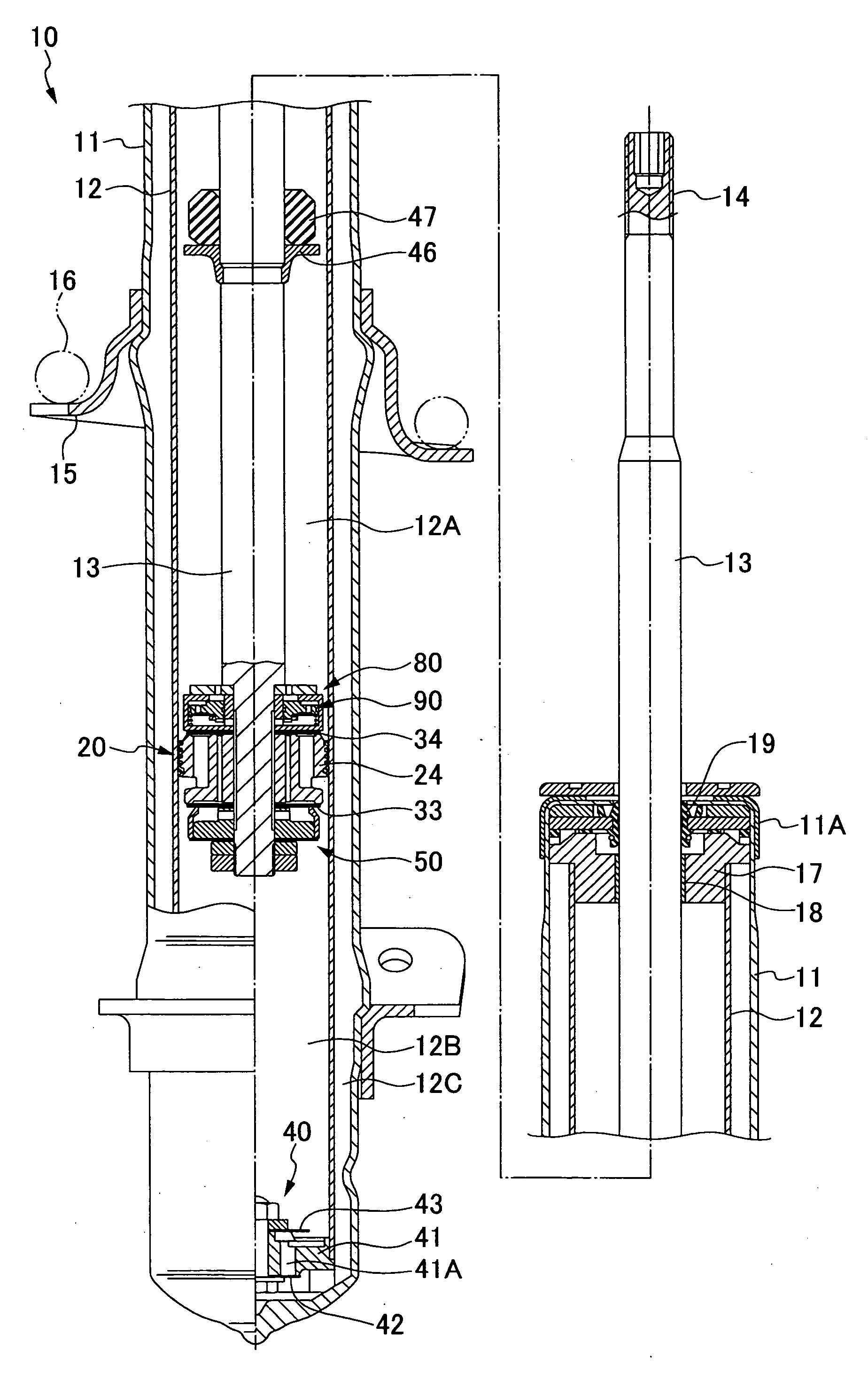
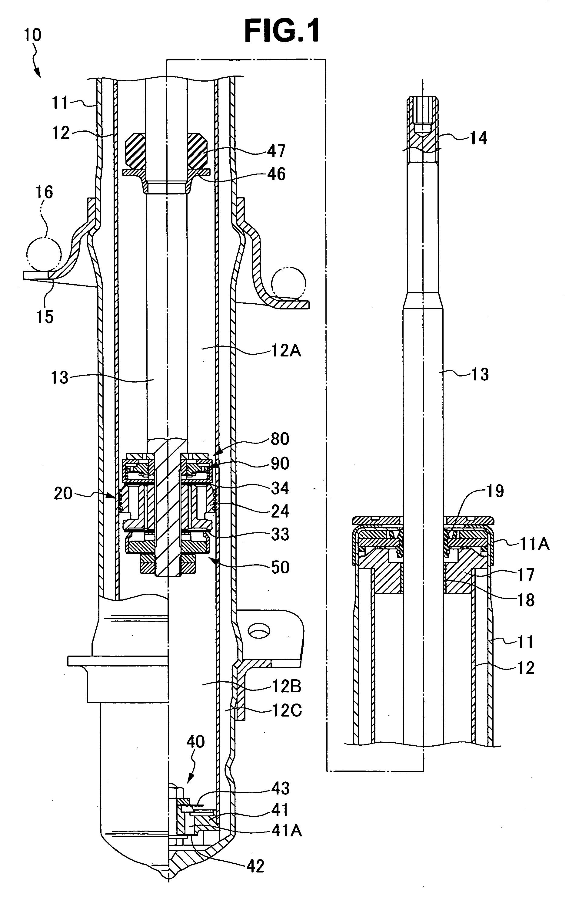
[0016]The damping force adjusting type hydraulic shock absorber 10 is of a double cylinder type in which a damper tube 11 has a cylinder 12 built-in, as shown in FIG. 1. It is structured such that a piston rod 13 is inserted to the cylinder 12 accommodating an oil liquid therein, an axle side attaching portion is provided in a lower portion of the damper tube 11, and a vehicle body side attaching portion 14 is provided in an upper portion of the piston rod 13, thereby constructing a suspension apparatus of a vehicle.
[0017]The hydraulic shock absorber 10 interposes a suspension spring 16 between a lower spring seat 15 in an outer periphery of the damper tube 11, and an upper spring seat (not shown) provided in the vehicle body side attaching portion 14 in the upper end portion of the piston rod 13.
[0018]The hydraulic shock absorber 10 pinches and fixes a rod guide 17, a bush 18 and an oil seal 19 for the piston rod 13 inserted to the cylinder 12 between a...
embodiment 2
(Embodiment 2) (FIG. 4)
[0055]The hydraulic shock absorber 10 shown in FIG. 4 is provided with a compression side damping force adjusting apparatus 100 for adjusting the compression side damping force of the piston valve apparatus 20. In this case, in the piston valve apparatus 20 of the hydraulic shock absorber 10, the spacer 22, the valve stopper 23, the compression side damping valve 34, the piston 24, the expansion side damping valve 33, a valve case 130 for a blow valve 140 mentioned below and the spacer 27 are installed to the outer periphery of the thread portion 21 of the piston rod 13. They are pinched and fixed with respect to the base end step portion of the thread portion 21 by a nut 28 engaged with the thread portion 21.
[0056]The compression side damping force adjusting apparatus 100 is provided with a compression side back pressure chamber 101 in a back surface side with respect to the compression side flow path 32 of the compression side damping valve 34, as shown in F...
embodiment 3
(Embodiment 3) (FIG. 5)
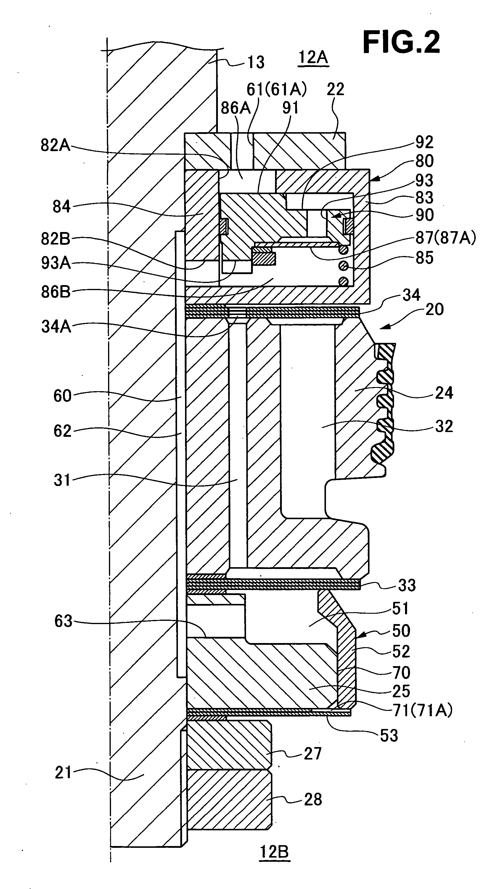
[0083]The hydraulic shock absorber 10 shown in FIG. 5 has an expansion side damping force adjusting apparatus 150 which is substantially the same as the expansion side damping force adjusting apparatus 50 in the embodiment 1. The expansion side damping force adjusting apparatus 150 is different from the expansion side damping force adjusting apparatus 50 in that the backup collar 52 and the plate spring 53 forming the expansion side back pressure chamber 51, and the blow valve 90 incorporated in the valve case 80, are provided between the expansion side damping valve 33 provided in the lower side surface of the piston 24 and the space 27.
[0084]In other words, the expansion side damping force adjusting apparatus 150 is structured such that the valve case 80 (the tube box 83 and the hollow shaft 84) and the plate spring 53 are pinched and fixed between the expansion side damping valve 33 and the space 27 in the outer periphery of the piston rod 13, and the backu...
PUM
 Abstract
Description
Claims
Application Information