Airbag for knee protection

a knee protection and airbag technology, applied in the field of airbags, can solve the problems of increasing time and cost for manufacturing airbags, easy loss of inner pressure, etc., and achieve the effect of wide width and reduced number of parts of airbags

Inactive Publication Date: 2009-04-02
TOYODA GOSEI CO LTD
View PDF10 Cites 45 Cited by
  • Summary
  • Abstract
  • Description
  • Claims
  • Application Information

AI Technical Summary

Benefits of technology

[0032]Moreover, the number of parts of the airbag will be reduced by providing the second tether as part of, that is, as integral with a base cloth for forming the vehicle body side wall of the lower inflatable chamber.
[0033]Furthermore, if a width of the second tether in a transverse direction is smaller than an assumed distance between knees of the occupant, the second tether will not interrupt the mainstreams of inflation gas located on the left and right regions of the airbag, and therefore conducing to quick inflation of the upper inflatable chamber. However, the second tether may be configured to have a wider width in the transverse direction on condition that it does not interrupt the mainstreams of inflation gas passing through left and right regions of the airbag for the upper inflatable chamber.

Problems solved by technology

The latter airbag has a coating for preventing gas leakage and abrupt drop in the inner pressure since the airbag is designed to be thin and have a small volume with the two tethers and therefore may easily lose the inner pressure if gas leaks.
The design of the conventional airbag that has two tethers and a coating has increased time and cost for manufacturing an airbag, and therefore, there has been a demand for an airbag that has a reduced number of tethers and is made of woven fabric having no coating.

Method used


Image

  • Airbag for knee protection
  • Airbag for knee protection
  • Airbag for knee protection

Examples


first embodiment

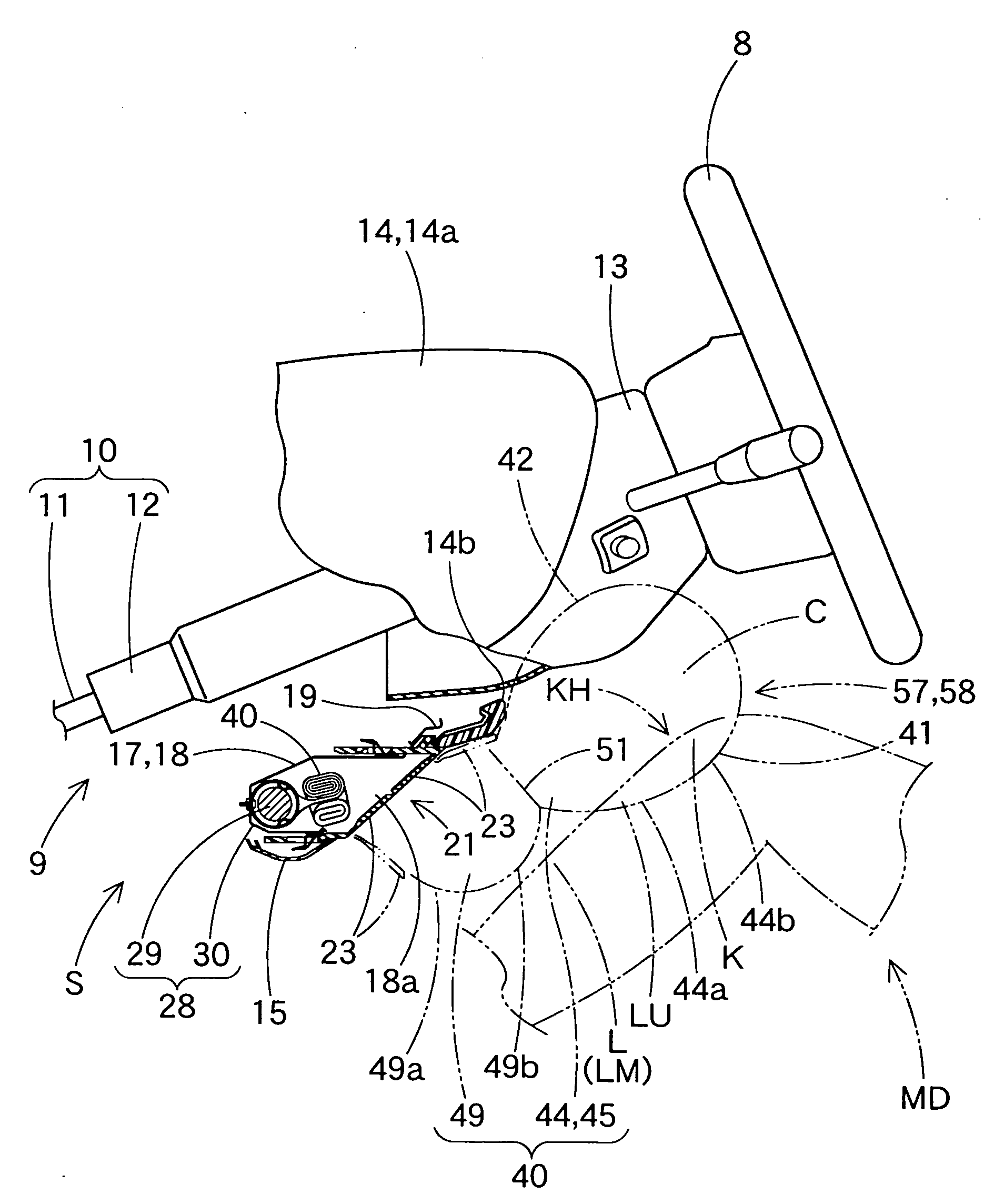
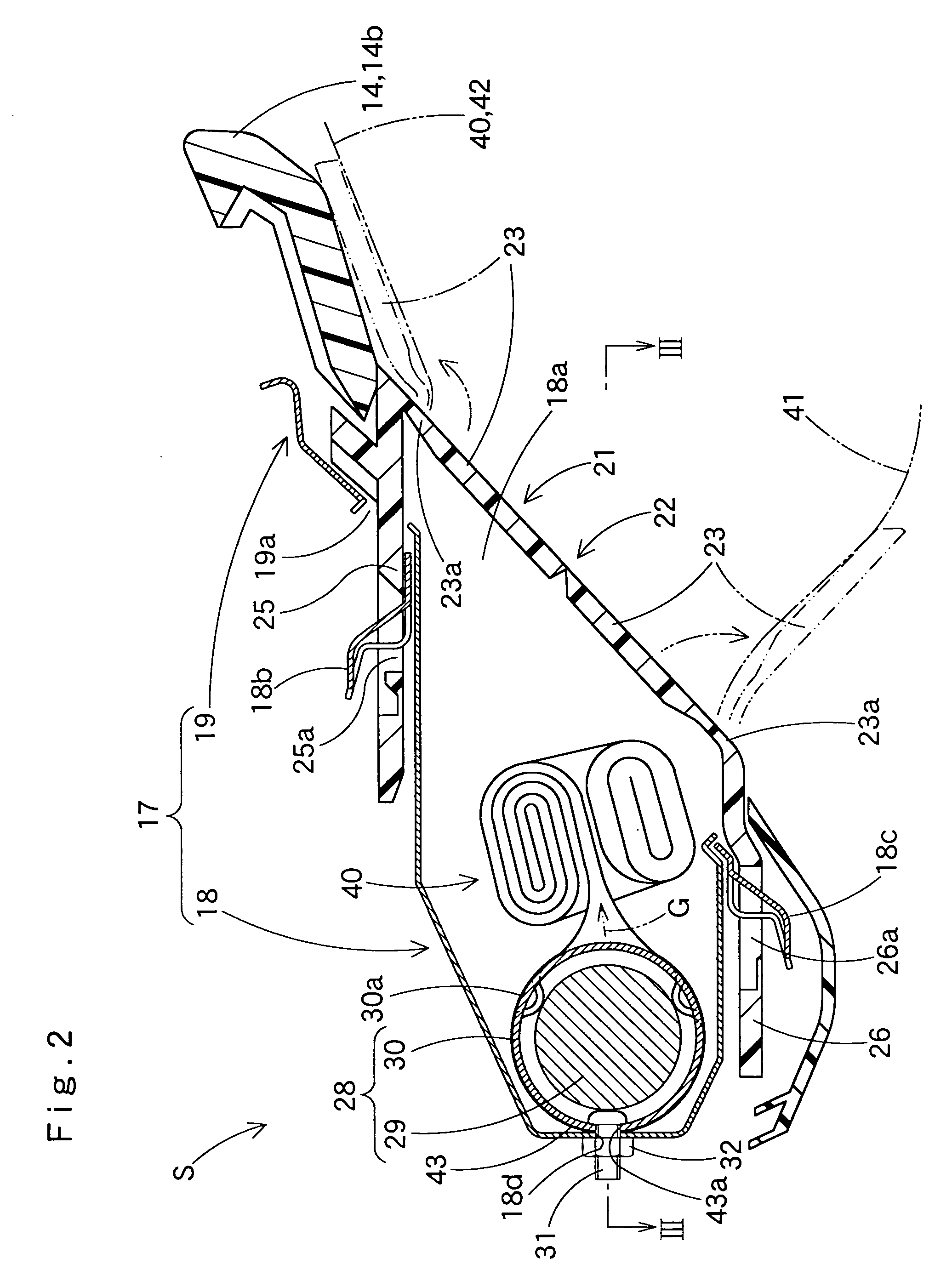
[0059]An airbag 40 according to the invention is employed in a knee-protecting airbag apparatus S shown in FIGS. 1 to 4. As shown in FIGS. 1 and 4, the airbag apparatus S is located below a steering column 9 in front of a driver's seat for protecting knees K of a driver or occupant MD.

[0060]As shown in FIG. 1, the steering column 9 includes a column body 10 connected to a steering wheel 8 and a column cover 13 that covers the column body 10 below the steering wheel 8. The column body 10 includes a main shaft 11 and a column tube 12 mounted around the main shaft 11. The column cover 13 is made from synthetic resin and has a generally square tubular shape projecting rearward from an instrument panel or dashboard while covering the column body 10 (FIG. 4).

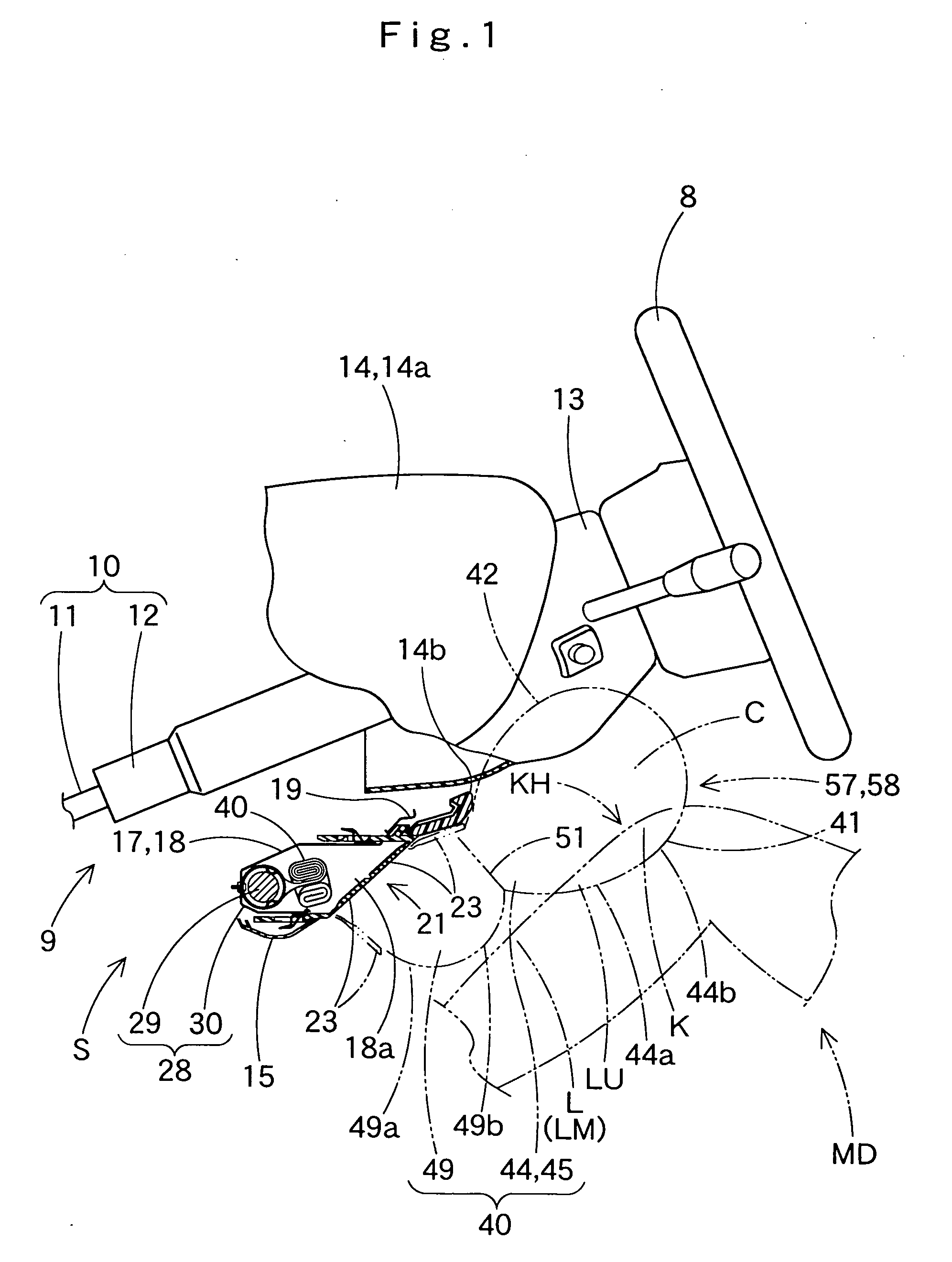
[0061]As shown in FIGS. 1 to 3, the airbag apparatus S includes in addition to the airbag 40 an inflator 28 for supplying the airbag 40 with inflation gas G, a case 17 that houses the inflator 28 and airbag 40 in a folded state and ha...

second embodiment

[0097]The airbag 40A includes proximate an upper end 40a at full inflation a knee-arresting portion 45 that has a greater thickness in an opposing direction of the walls 41 and 42 than other regions of the airbag 40A for receiving knees K as shown in FIGS. 19, 21, 22A to 22C. The knee-arresting portion 45 of the second embodiment includes on a rear face 44a an arresting area 46 that extends widely in four directions for receiving entire front faces of the vicinity of upper ends LU of shins L and knees K of a driver MD. The airbag 40A further internally includes a first tether 51 and a second tether 52 that connects the knee-side wall 41 and vehicle body side wall 42 for controlling a thickness of the airbag 40A in an opposing direction of the walls 41 and 42 at airbag inflation. The first tether 51 acts to partition the airbag 40 into a plurality of chambers arranged one above another whereas the second tether 52 makes a part of the arresting area 46 dent forward so as to inhibit re...


PUM


Abstract

An airbag for knee protection internally includes a first tether that connects a knee-side wall and a vehicle body side wall by a connecting distance of 50 to 90 mm and partitions the airbag into an upper inflatable chamber and a lower inflatable chamber. The mainstreams of inflation gas heading to the upper inflatable chamber from the lower are located proximate left and right ends of the airbag. The upper inflatable chamber has an outer diameter of 150 to 220 mm at full airbag inflation. The lower inflatable chamber includes on the vehicle body side wall a mounting portion by which the airbag is secured to the case and is designed such that a top of its rear face is dislocated forward relative to that of the upper inflatable chamber by 10 to 70 mm at full inflation of the airbag.

Description

[0001]The present application claims priority from Japanese Patent Application No. 2007-252567 of Imaeda et al., filed on Sep. 27, 2007 and Japanese Patent Application No. 2007-252597 of Imaeda, filed on Sep. 27, 2007, the disclosures of which are hereby incorporated into the present application by reference.BACKGROUND OF THE INVENTION[0002]1. Field of the Invention[0003]The present invention relates to an airbag suitable for use in a knee-protecting airbag apparatus for protecting knees of a vehicle occupant such as a driver or a front seat passenger in the event of impact of vehicle.[0004]2. Description of the Related Art[0005]JP 2006-131186 discloses a planar airbag for knee protection for deployment between a space between knees of a vehicle occupant and vehicle parts in a plate-like shape. The airbag includes a knee-side wall and a vehicle body side wall of the same contour connected together by a peripheral region and a tether that controls a distance between the knee-side wal...

Claims


Application Information

Patent Timeline
Patent Type & Authority Applications(United States)
IPC IPC(8): B60R21/16B60R21/2165B60R21/231
CPCB60R21/2032B60R21/206B60R21/2165B60R21/2171B60R2021/23509B60R21/237B60R2021/23169B60R2021/23324B60R21/231
Inventor IMAEDA, HIROKISAKAKIDA, KATSUMI
Owner TOYODA GOSEI CO LTD
Why Eureka
Try Eureka