Microwave Linked Laser Control System and Apparatus for Drilling and Boring Operations

a laser control system and laser control technology, applied in the direction of instruments, surveying, borehole/well accessories, etc., can solve the problem of often non-steerable methods

Inactive Publication Date: 2009-04-02
CARTWRIGHT JASON AUSTIN
View PDF11 Cites 11 Cited by
  • Summary
  • Abstract
  • Description
  • Claims
  • Application Information

AI Technical Summary

Problems solved by technology

In other trenchless technology operations, such as pipejacking and pipe ramming, the method is often non-steerable, and pipes installed by these methods are laid straight.

Method used


Image

  • Microwave Linked Laser Control System and Apparatus for Drilling and Boring Operations
  • Microwave Linked Laser Control System and Apparatus for Drilling and Boring Operations
  • Microwave Linked Laser Control System and Apparatus for Drilling and Boring Operations

Examples


Embodiment Construction

[0020]For a general understanding of the present invention, reference is made to the drawings. In the drawings, like reference numerals have been used throughout to designate identical elements.

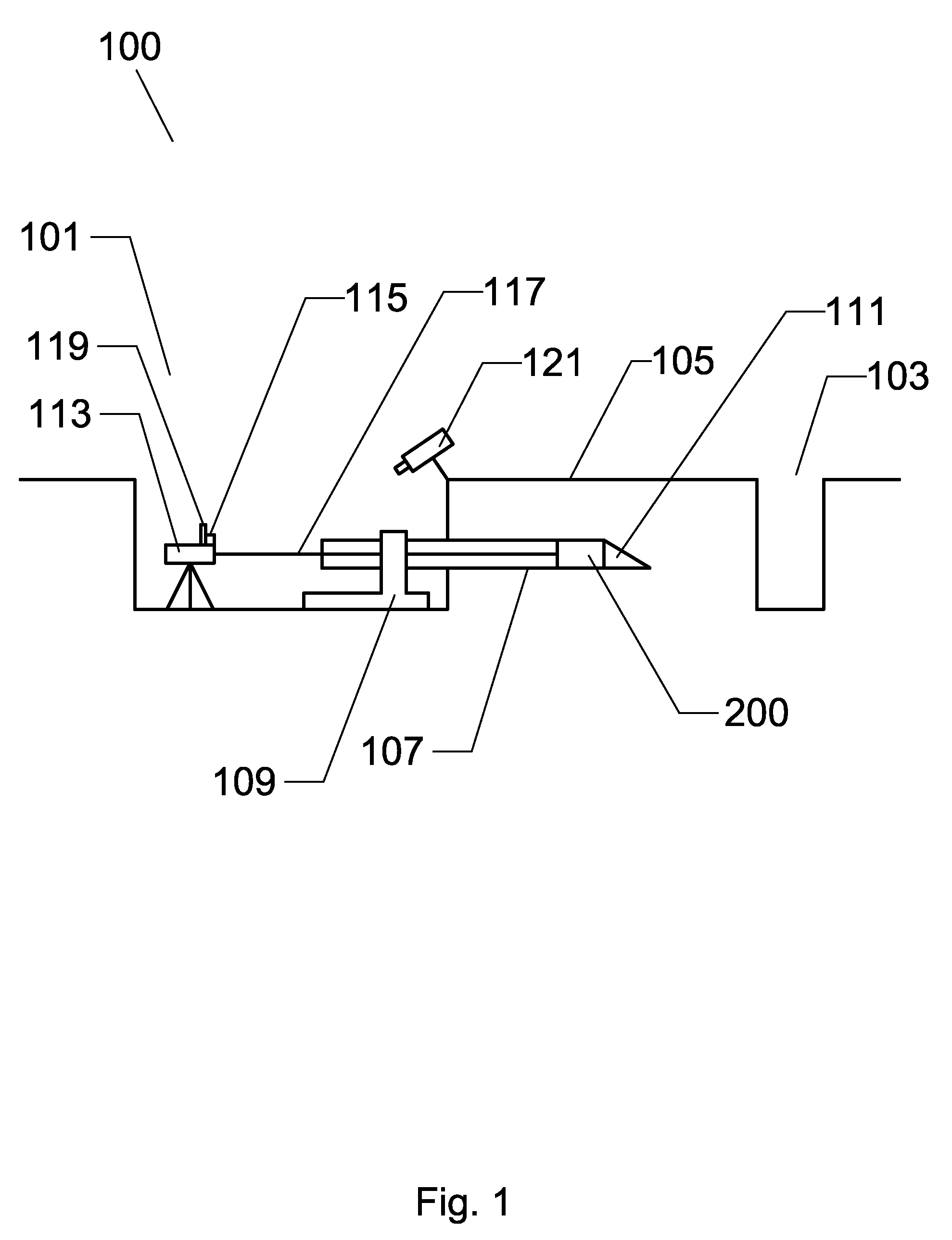
[0021]FIG. 1 is a diagram of a laser controlled trenchless operation. In a horizontal trenchless operation, it is common to have an insertion pit 101 and a receiving pit 103 that correspond with the origination and the termination of the trenchless operation or a segment thereof. The insertion pit 101 and the receiving pit 103 are typically excavated and often times reinforced for worker safety. If the trenchless operation is performed on a slope, one or both of the insertion pit 101 and the receiving pit 103 may not be necessary. An example of such an application is the trenchless installation of a culvert pipe under a raised railroad bed where trenchless technology is used to prevent settling or disruption of the railroad bed. The raised railroad bed has slopes on either side of the railroa...


PUM


Abstract

A laser control system and apparatus for guiding a drilling or boring operation during a trenchless technology implementation. In most if not all trenchless technology applications, direction of the pipe or utility structure through the earth is of utmost importance. Proper directional guidance throughout the trenchless technology implementation ensures not only that the resulting utility infrastructure is placed properly, but also ensures that the trenchless technology operation, does not hit or otherwise damage (such as through vibrations) existing utilities and other underground objects. The laser control system and apparatus of the present invention comprises a laser, a housing having a laser sight, a camera in optical communication with the laser sight a microwave transmitter having an antenna, with the transmitter being operatively coupled to the camera, and a microwave receiver.

Description

CROSS-REFERENCE TO RELATED PATENT APPLICATIONS[0001]This application claims the benefit of the filing date of U.S. Provisional Patent Application No. 60 / 976,405 filed on Sep. 28, 2007.BACKGROUND OF THE INVENTION[0002]1. Field of the Invention[0003]This invention relates generally to control systems for drilling and boring operations, and more particularly to a microwave linked laser control system and apparatus for drilling and boring operations.[0004]2. Description of Related Art[0005]Trenchless technology is a growing field that includes a wide variety of methods and techniques for installing and rehabilitating underground infrastructure with minimal surface disruption and without the destruction and subsequent rebuilding of essential infrastructure that is common with trenching and excavation. Examples of trenchless technologies include, but are not limited to, microtunneling, pipejacking, pipe ramming, sliplining, guided boring, haul systems, tunnel boring, and earth pressure ba...

Claims


Application Information

Patent Timeline
Patent Type & Authority Applications(United States)
IPC IPC(8): G01V3/00E21B47/01
CPCE21B47/02224E21B7/046E21B47/0232
Inventor CARTWRIGHT, JASON AUSTIN
Owner CARTWRIGHT JASON AUSTIN
Why Eureka
Try Eureka