Television camera system
- Summary
- Abstract
- Description
- Claims
- Application Information
AI Technical Summary
Benefits of technology
Problems solved by technology
Method used
Image
Examples
first embodiment
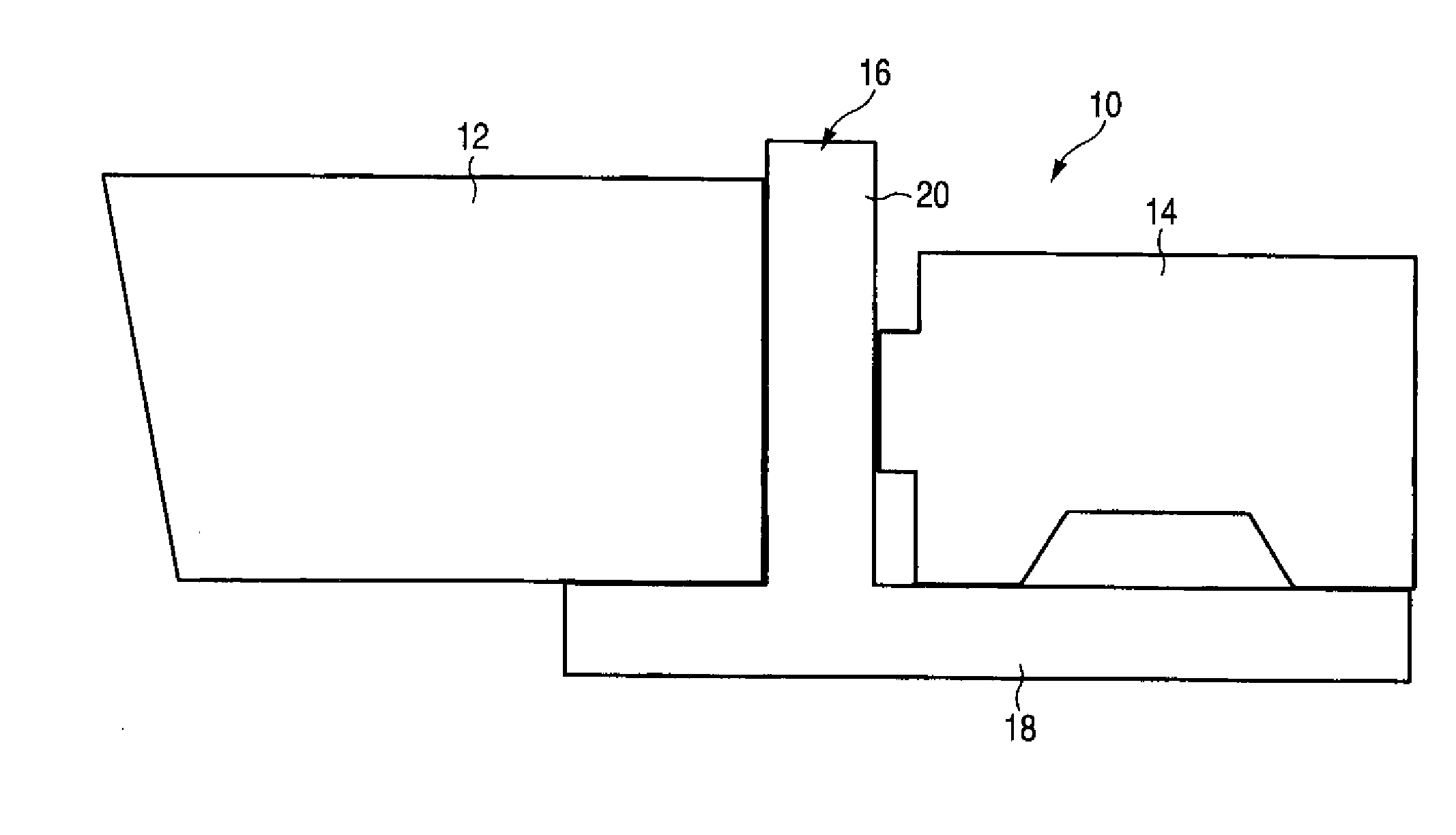
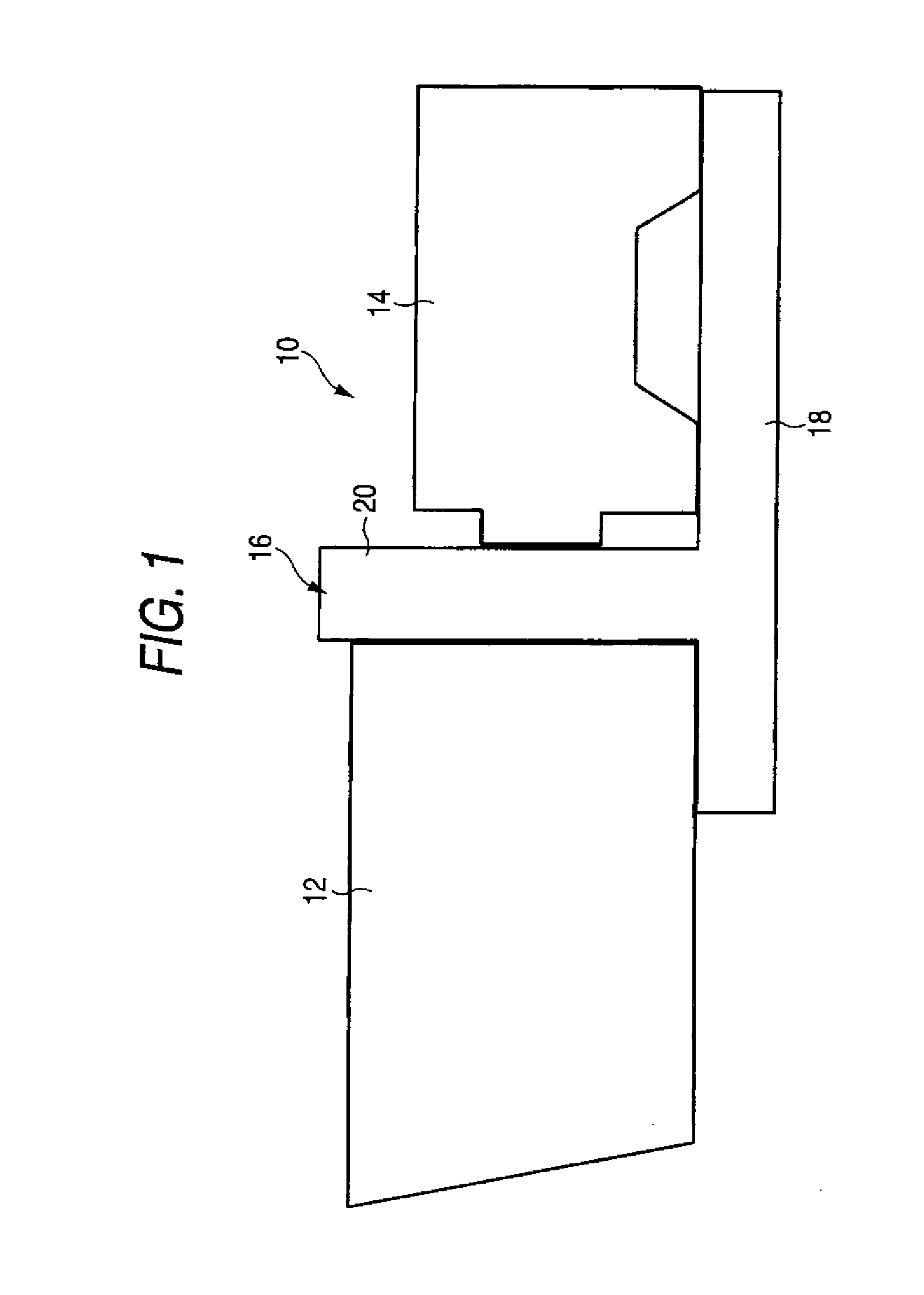
[0060]FIG. 4 is a view illustrating a connection mode, of electrical connectors among devices wherein signal transmission between the EFP lens 12 and the ENG camera 14 can be performed based on both of the parallel communication and the serial communication. Also, the same reference numerals are assigned to elements which are the same as those in FIG. 2, and detailed description thereof will be omitted.
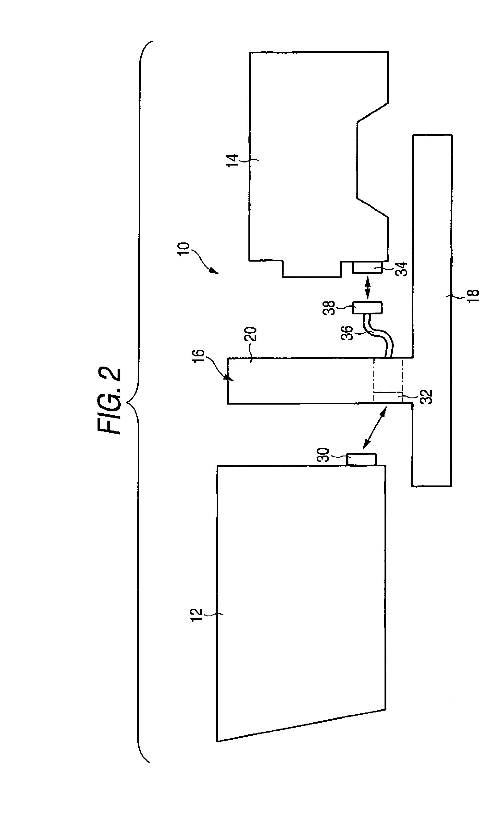
[0061]In the figure, when the EFP lens 12 is fixed on the lens supporter 16, similarly to FIG. 2, the 36-pin connector 30 disposed on the rear side of the EFP lens 12 is connected to the 36-pin connector 32 disposed on the front side of the partition section 20 of the lens supporter 16.
[0062]The cable 36 extends from the rear side of the partition section 20 of the lens supporter 16 similarly to FIG. 2. At the end portion of the cable 36, the 12-pin camera-side connector 38 connectable to the connector 34 of the ENG camera 14 is provided. Similarly to FIG. 2, when the parallel commun...
second embodiment
[0071]FIG. 6 is a view illustrating a connection mode, of electrical connectors among devices wherein signal transmission between the EFP lens 12 and the ENG camera 14 can be performed based on both of the parallel communication and the serial communication. The same reference numerals are assigned to elements which are the same as or similar to those in FIG. 4, and detailed description thereof will be omitted.
[0072]In the figure, when the EFP lens 12 is fixed on the lens supporter 16, similarly to FIGS. 2 and 4, the 36-pin connector 30 disposed on the rear side of the EFP lens 12 is connected to the 36-pin connector 32 disposed on the front side of the partition section 20 of the lens supporter 16.
[0073]Unlike FIG. 4, on the rear side of the partition section 20 of the lens supporter 16, the cables 36 and 60 are not provided, and the serial connector 62 of 12 pins and the parallel connector 38 of 12 pins are directly provided on the wall thereof. A 12-pin connector 72 disposed at ...
third embodiment
[0081]FIG. 8 is a view illustrating a connection mode, of electrical connectors among devices wherein signal transmission between the EFP lens 12 and the ENG camera 14 can be performed based on both of the parallel communication and the serial communication. The same reference numerals are assigned to elements which are the same as or similar to those in FIG. 2, and detailed description thereof will be omitted.
[0082]In the figure, when the EFP lens 12 is fixed on the lens supporter 16, similarly to FIG. 2, the 36-pin connector 30 disposed on the rear side of the EFP lens 12 is connected to the 36-pin connector 32 disposed on the front side of the partition section 20 of the lens supporter 16.
[0083]The cable 36 extends from the rear side of the partition section 20 of the lens supporter 16 similarly to FIG. 2. At the end portion of the cable 36, the 12-pin camera-side connector 38 connectable to the connector 34 of the ENG camera 14 is provided. Similarly to FIG. 2, when the paralle...
PUM
 Abstract
Description
Claims
Application Information
 - R&D
- Intellectual Property
- Life Sciences
- Materials
- Tech Scout
- Unparalleled Data Quality
- Higher Quality Content
- 60% Fewer Hallucinations
Browse by: Latest US Patents, China's latest patents, Technical Efficacy Thesaurus, Application Domain, Technology Topic, Popular Technical Reports.
© 2025 PatSnap. All rights reserved.Legal|Privacy policy|Modern Slavery Act Transparency Statement|Sitemap|About US| Contact US: help@patsnap.com


