
Superheterodyne seismic vibrator and method

a vibrator and superheterodyne technology, applied in the field of vibrations, can solve the problems of difficult control of such motion so as to faithfully correspond to the electrical control signal, the vibrator known in the art is limited in the highest frequency it can accurately generate, and the conventional vibrator cannot operate effectively above about 150 hz

Inactive Publication Date: 2009-04-02
PGS ONSHORE INC
View PDF16 Cites 17 Cited by
  • Summary
  • Abstract
  • Description
  • Claims
  • Application Information

AI Technical Summary

Problems solved by technology

A particular limitation to vibrator seismic sources known in the art relates to generating low frequency seismic energy, typically less than about 8 Hz.
Controlling such motion so that it faithfully corresponds to the electrical control signal has also proven to be difficult.
Additionally, vibrators known in the art are limited with respect to the highest frequencies they can accurately generate because of coupling difficulties between the driver and the acoustic radiating the surface and limitations in the speed at which hydraulic mechanism can react.
Typically, conventional vibrators cannot operate effectively above about 150 Hz.

Method used


Image

  • Superheterodyne seismic vibrator and method
  • Superheterodyne seismic vibrator and method

Examples


Embodiment Construction

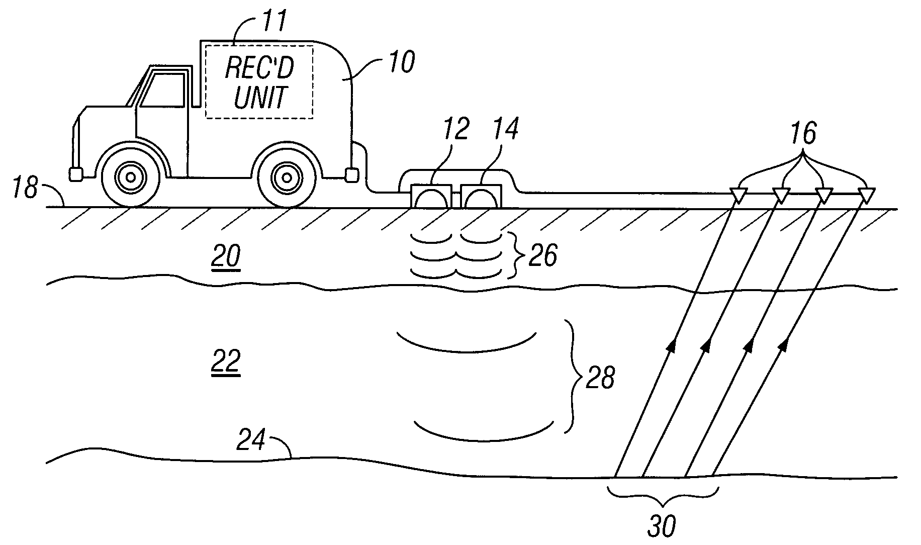
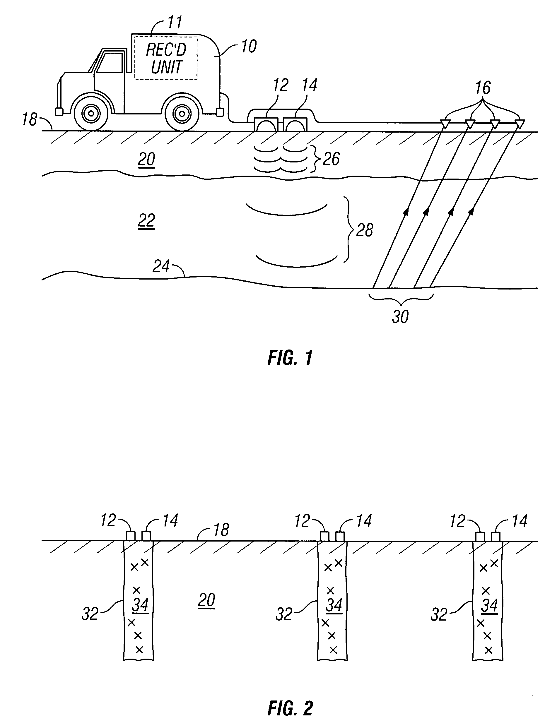
[0013]An example seismic energy source and recording system in accordance with the invention is shown schematically in FIG. 1. A seismic recording unit 11, which in the present example is disposed in a truck 10 or similar vehicle, may include devices (none shown separately) for controlling one or more seismic energy sources which may be acoustic radiators 12, 14 (explained below), and for determining geodetic position of the recording unit 11 and associated devices, such as the seismic source and each of a plurality of seismic sensors 16. The recording unit 11 typically also includes a recording device (not shown separately) for recording signals produced by each of the seismic sensors 16 in response to seismic energy imparted into the Earth's subsurface. The truck 10, the acoustic radiators 12, 14 and the seismic sensors 16 are shown disposed on the ground surface 18 on dry land. Use of a method and system according to the invention is not limited to the example shown in FIG. 1 of ...


PUM


Abstract

A seismic energy source includes at least a first and a second acoustic radiator operatively coupled to a non-linear medium proximate an upper limit of formations in the Earth's subsurface. The first and second acoustic radiators are configured to convert electrical energy directly into acoustic energy. The source includes means for operating the first and the second acoustic radiator at respective first and second frequencies. The first and second frequencies are selected such that substantially no acoustic energy propagates through the non-linear medium. The first and the second frequencies are selected such that a difference therebetween is swept through a range of frequencies of seismic energy capable of propagating through the Earth's subsurface to at least one acoustic impedance boundary within the Earth's subsurface.

Description

CROSS-REFERENCE TO RELATED APPLICATIONS[0001]Not applicable.STATEMENT REGARDING FEDERALLY SPONSORED RESEARCH OR DEVELOPMENT[0002]Not applicable.BACKGROUND OF THE INVENTION[0003]1. Field of the Invention[0004]The invention relates generally to the field of vibrators used as sources of seismic energy for surveying the Earth's subsurface. More particularly, the invention relates to vibrators that use the superheterodyne principle to produce very low frequency seismic energy.[0005]2. Background Art[0006]Vibrator-type seismic energy sources known in the art impart seismic energy into the Earth's subsurface by moving a radiating surface in a particular manner. See, for example, U.S. Pat. No. 3,863,202 issued to Landrum, Jr. In one type of implementation, the radiating surface is coupled to a control system including a hydraulic ram and a control valve that selectively applies hydraulic pressure to each side of the hydraulic ram. The control valve is typically electrically operated. Electr...

Claims


Application Information

Patent Timeline
Patent Type & Authority Applications(United States)
IPC IPC(8): G01V1/40
CPCG01V2210/588G01V1/005
Inventor SCOTT, GARY LEEPRAMIK, WILLIAM B.
Owner PGS ONSHORE INC
Learn More