
Finger Contact Detecting Apparatus, Finger Contact Detecting Method, Fingerprint Reading Apparatus and Fingerprint Reading Method

a finger contact and finger contact technology, applied in the field of finger contact detecting apparatus and finger contact detecting method, fingerprint reading apparatus, fingerprint reading method, etc., can solve the problem of inadequacies in the determination method described above, and achieve the effect of accurate finger contact detection

Active Publication Date: 2009-04-02
MITSUMI ELECTRIC CO LTD
View PDF3 Cites 10 Cited by
  • Summary
  • Abstract
  • Description
  • Claims
  • Application Information

AI Technical Summary

Benefits of technology

[0017]Thereby, finger contact detection can be reliably performed, and a fingerprint image can be obtained at the time when the finger separates from the detecting unit.
[0021]According to another aspect of the invention, an accurate detection of finger contact can be performed.

Problems solved by technology

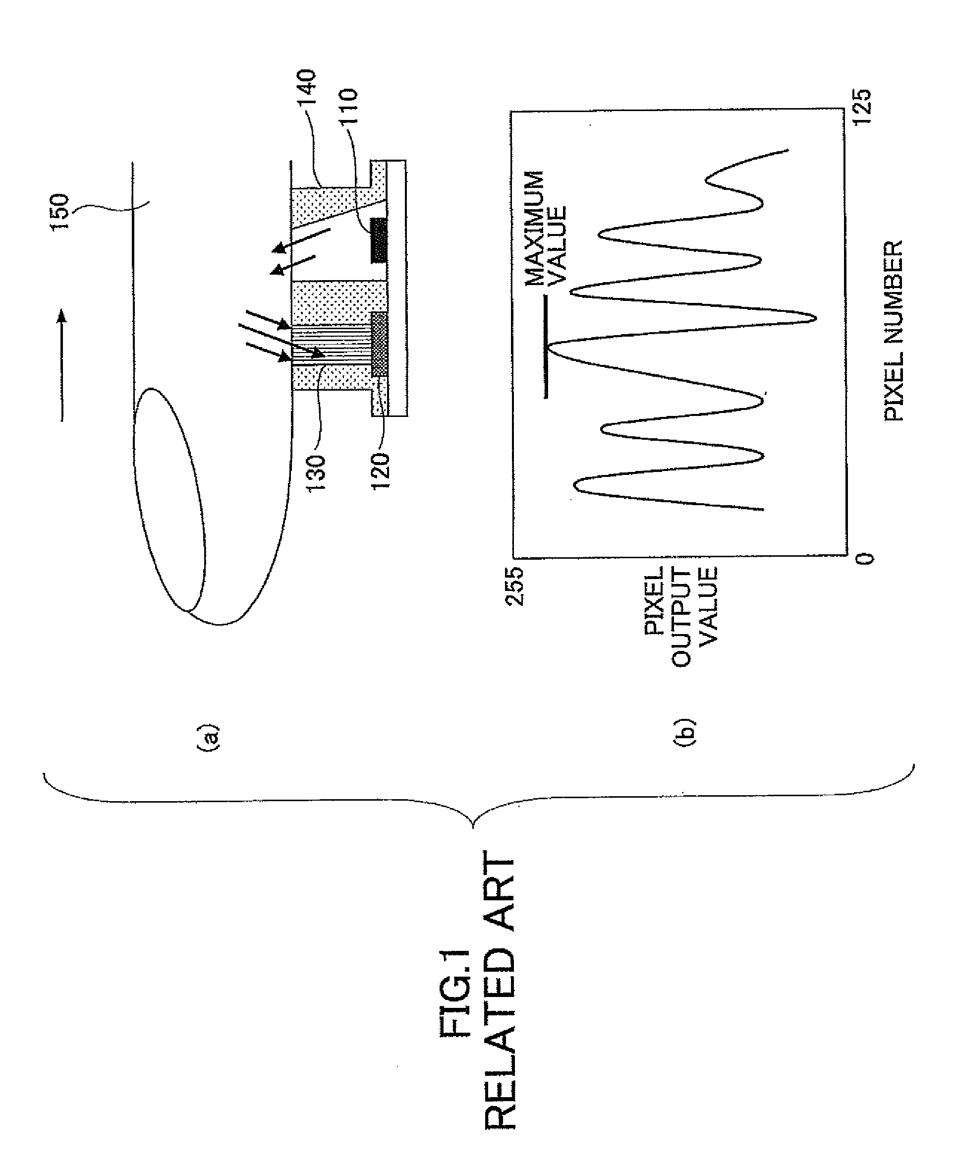
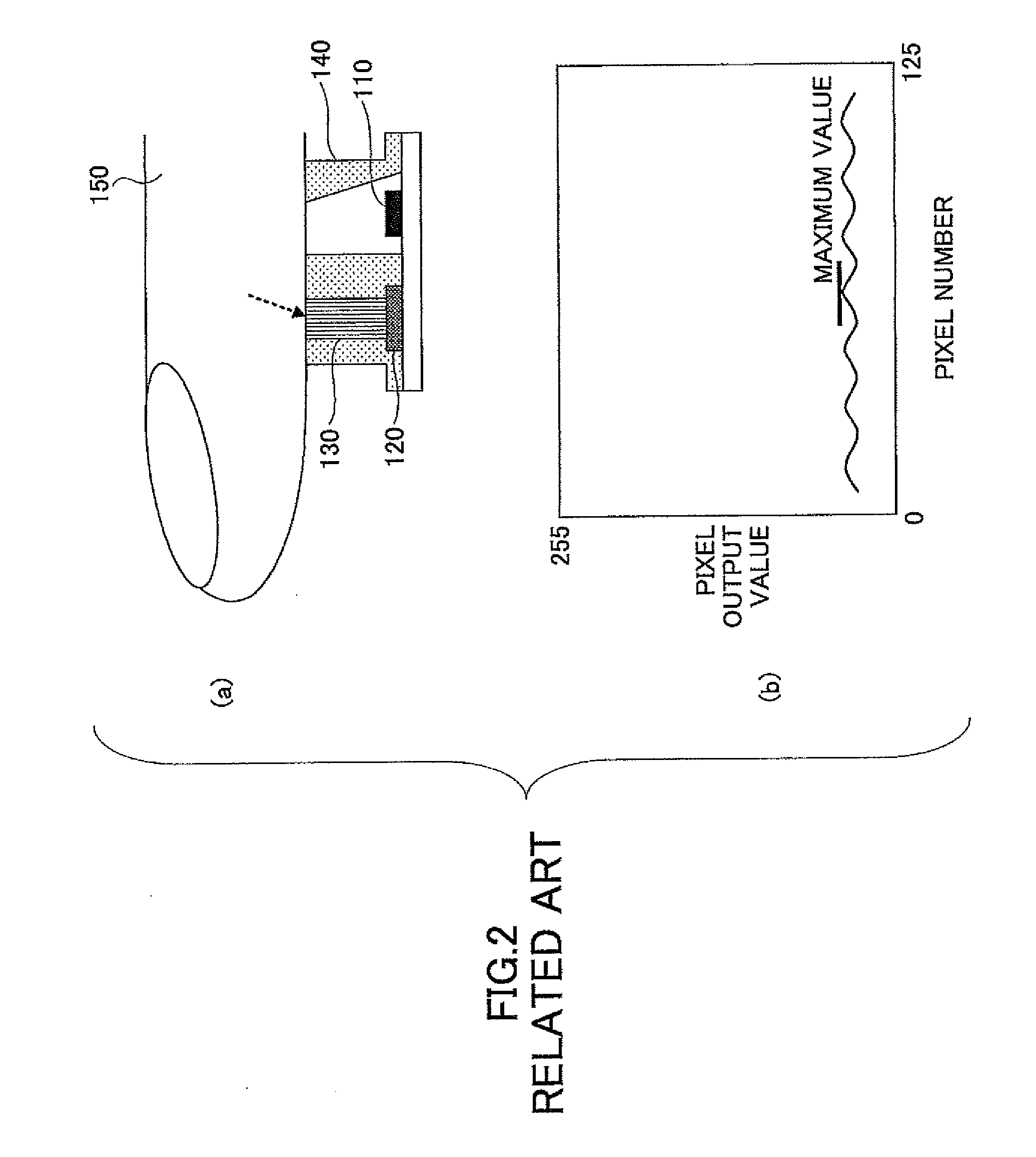
However, related art devices shown in FIG. 1 and FIG. 2 described above have a problem in that disturbing (background) light radiation causing frequent misdetection that the finger 150 is judged not to be on the line sensor 120 while the finger 150 is actually on the line sensor.
Thus, the determination method described above does not function appropriately.
Also, there is little consideration of the influence for the background light in the patent document 1 mentioned above, and there may be a similar problem causing misdetection under background light that a finger is judged not to be on a line sensor while the finger is actually on the line sensor.

Method used


Image

  • Finger Contact Detecting Apparatus, Finger Contact Detecting Method, Fingerprint Reading Apparatus and Fingerprint Reading Method
  • Finger Contact Detecting Apparatus, Finger Contact Detecting Method, Fingerprint Reading Apparatus and Fingerprint Reading Method
  • Finger Contact Detecting Apparatus, Finger Contact Detecting Method, Fingerprint Reading Apparatus and Fingerprint Reading Method

Examples


Embodiment Construction

[0035]Referring to figures, preferred embodiments are described in the following.

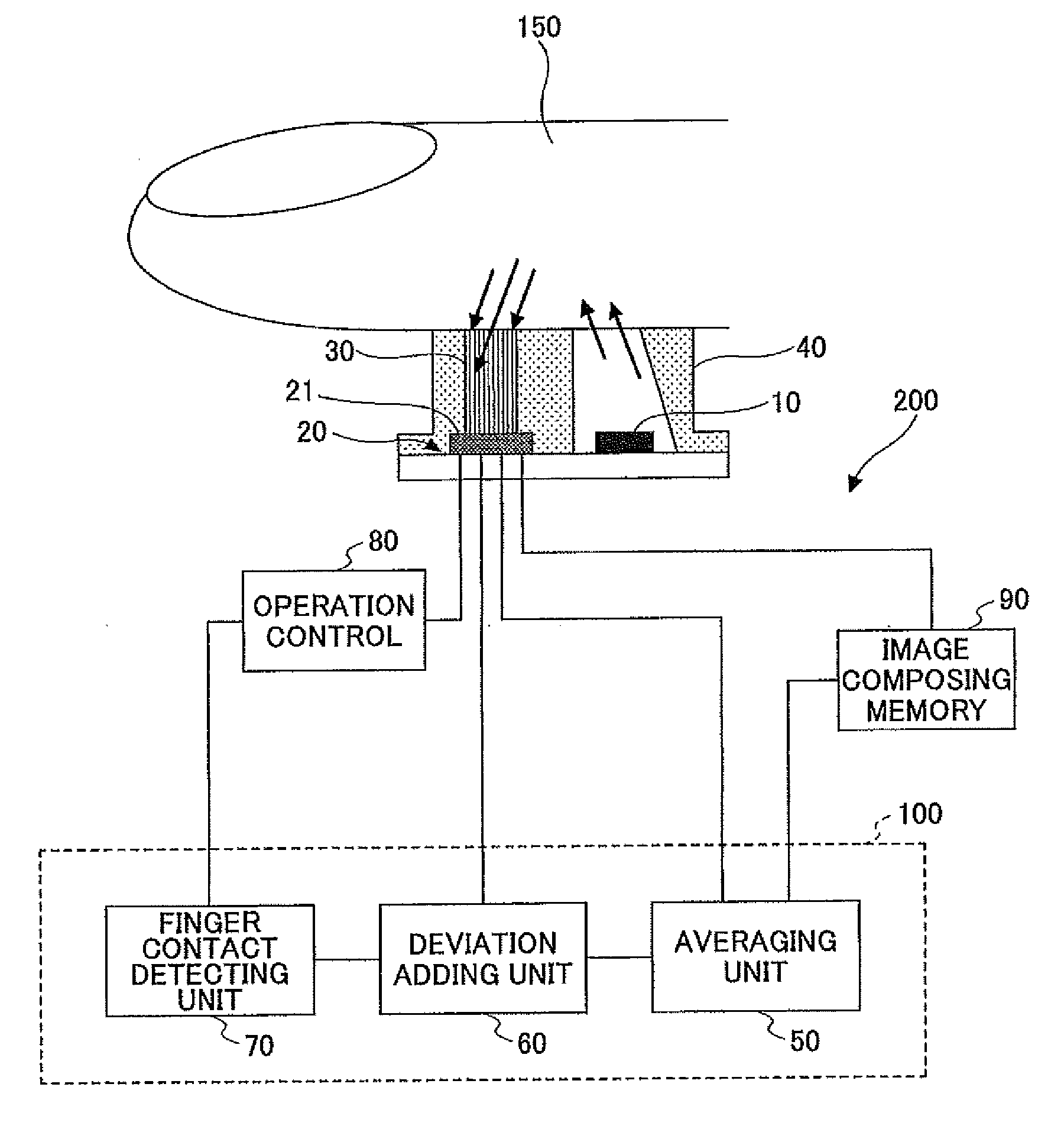
[0036]FIG. 3 is a drawing showing a concept of a constitution of a finger contact detecting apparatus 100 and a fingerprint reading apparatus 200 applying this embodiment. In FIG. 3, the finger contact detecting apparatus 100 includes a pixel data-averaging unit 50 (or an averaging unit 50), a deviation adding unit 60, and a finger contact detecting unit 70. Further, a fingerprint reading apparatus 200 may include a fingerprint sensor 20, an image composing memory 90, a light-emitting unit 10, an image guide 30, a frame 40, and an operation control unit 80 according to necessity.

[0037]The light-emitting unit 10 radiates output light to a finger 150. In order to collect a fingerprint image of the finger 150, a ridge pattern of a surface of the fingerprint needs to be read by radiating the output light (of the light-emitting unit 10) to the finger 150 and receiving reflected (or scattered) light from the ...


PUM


Abstract

A finger contact detecting apparatus, which detects a finger being swept on a fingerprint sensor of the finger contact detecting apparatus, the finger contact detecting apparatus including, a pixel data averaging unit calculating an average value of pixel data collected by the fingerprint sensor; a deviation adding unit calculating, based on the average value and respective pixel data of predetermined pixels obtained by the fingerprint sensor, a summation of deviations of the respective pixel data of the predetermined pixels; and a finger contact detecting unit determining whether the finger is separated from the fingerprint sensor based on the summation of deviations and a predetermined threshold value.

Description

BACKGROUND OF THE INVENTION[0001]1. Field of the Invention[0002]This invention relates to a finger contact detecting apparatus and a finger contact detecting method, a fingerprint reading apparatus, and a fingerprint reading method.[0003]2. Description of the Related Art[0004]A fingerprint reading apparatus including a line sensor with pixels arranged on a line is known. While a finger is swept on the line sensor, light is irradiated onto the finger with a LED (Light Emitting Diode) or the like, and the reflected light from the finger is detected with the line sensor to obtain a line image of the finger. A fingerprint image is then formed (composed) using the line image.[0005]Such a fingerprint reading apparatus obtains a subtraction (difference) between the maximum values of a fingerprint image data measured under LED light radiation and no LED light radiation, and determines whether the finger is separated from the line sensor based on a difference between the subtraction result a...

Claims


Application Information

Patent Timeline
Patent Type & Authority Applications(United States)
IPC IPC(8): G06K9/00
CPCG06K9/00026G06V40/1335
Inventor MIZUSHIMA, SATOSHITAHARA, YOSHINORI
Owner MITSUMI ELECTRIC CO LTD
Learn More