Multi-interface protocol analysis system

a protocol analysis and multi-interface technology, applied in the field of multi-interface protocol analysis system, can solve problems such as complex testing

Inactive Publication Date: 2009-04-02
VERIZON PATENT & LICENSING INC
View PDF11 Cites 76 Cited by
  • Summary
  • Abstract
  • Description
  • Claims
  • Application Information

AI Technical Summary

Problems solved by technology

Unfortunately, known protocol analyzers must be set up individually and can only analyze one circuit at a time, thereby complicating testing due to the ambiguity of where to place the units and what data would need to be captured and when the data would need to be captured.

Method used


Image

  • Multi-interface protocol analysis system
  • Multi-interface protocol analysis system
  • Multi-interface protocol analysis system

Examples


Embodiment Construction

[0007]The following detailed description of exemplary embodiments refers to the accompanying drawings. The same reference numbers in different drawings may identify the same or similar elements. Also, the following detailed description does not limit the invention.

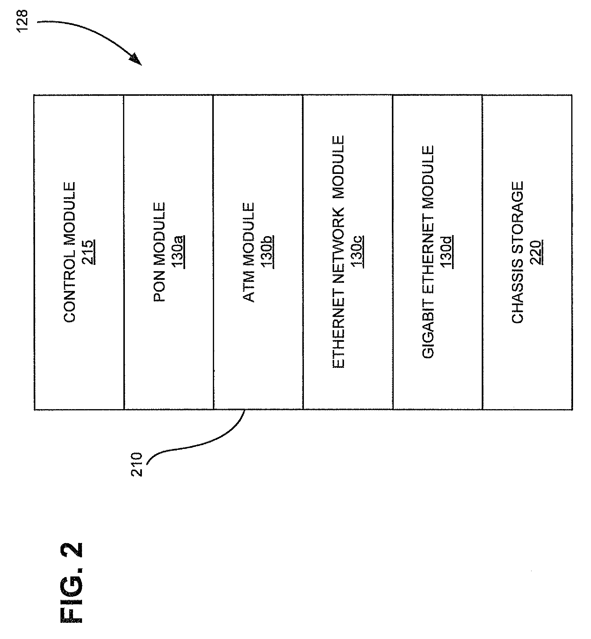
[0008]Implementations described herein provide for enhanced network testing by facilitating the monitoring and correlation of network information from a number of interface points. In one embodiment, interface modules associated with an optical line termination (OLT) unit may capture network information as it passes through each module. The network information may be collected and forwarded to a protocol analyzer for correlation and subsequent analysis.

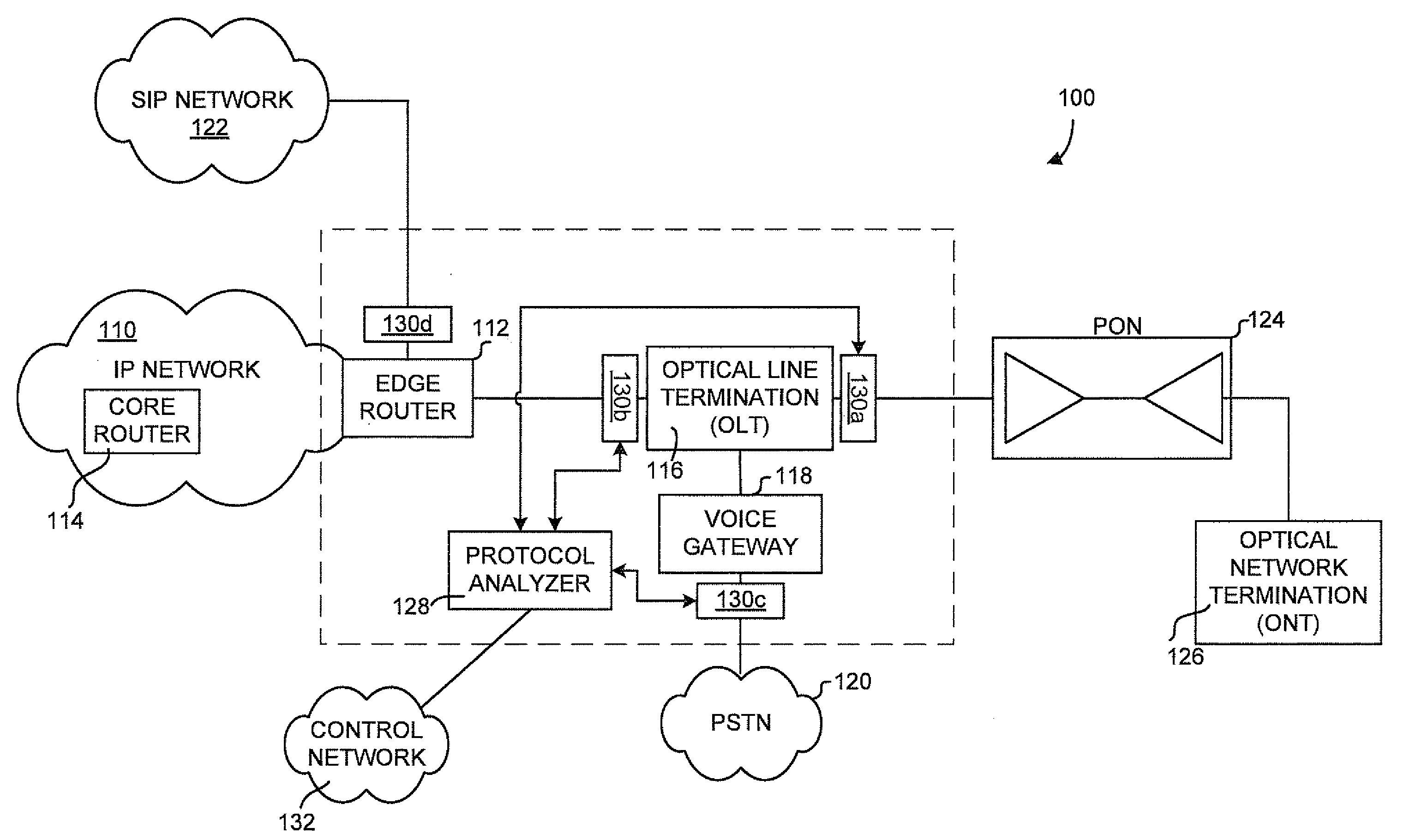
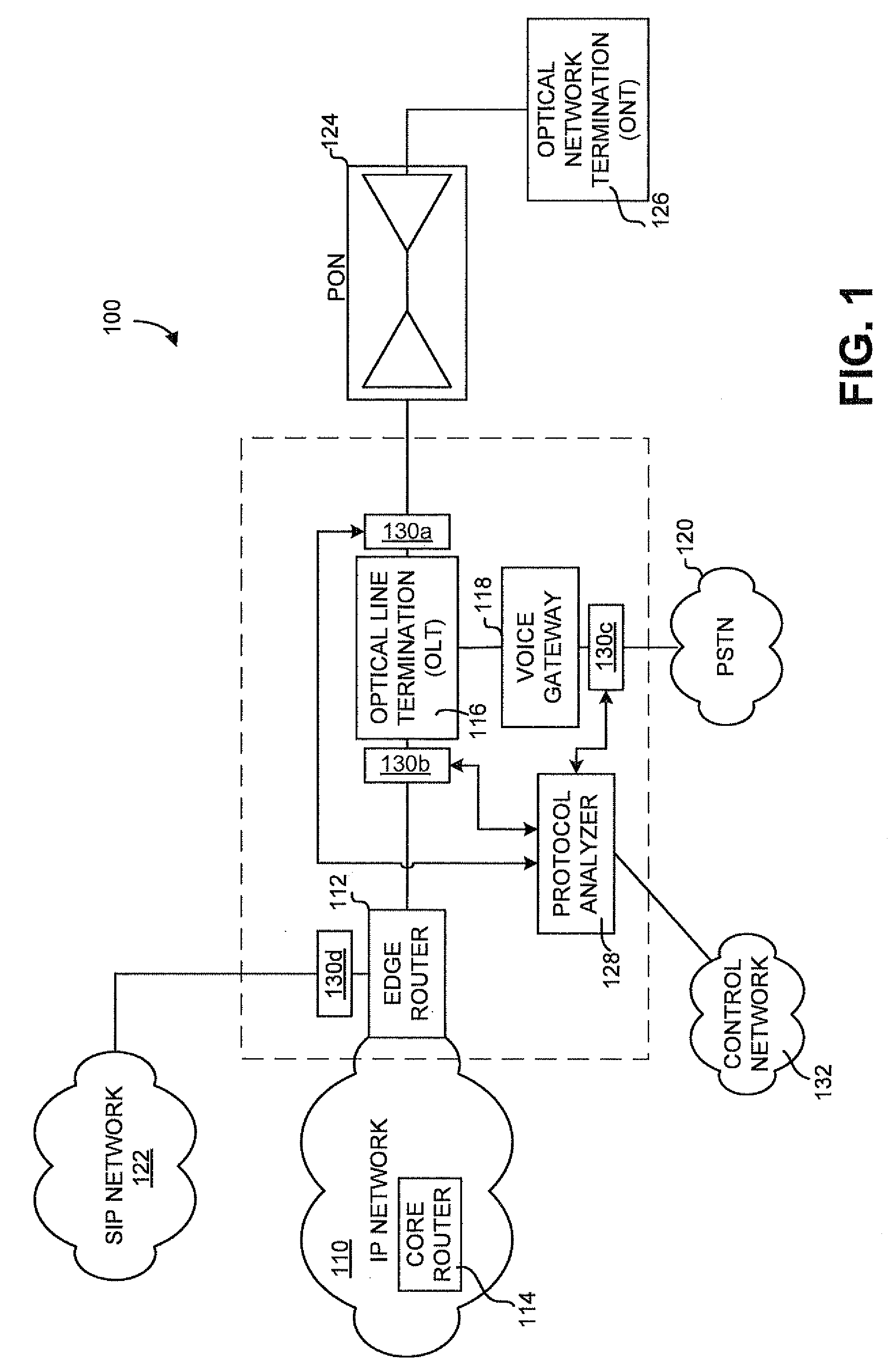
[0009]FIG. 1 is a diagram of an exemplary system in which embodiments described herein may be implemented. As illustrated, system 100 may include a first network 110, edge router 112, core router 114, OLT unit 116, voice gateway 118, public switched telephone network (PSTN) ...


PUM


Abstract

A device may include a first network module to capture network data at a first location in a network and a second network module to capture network data at a second location in the network different from the first location in the network. The device may include a control module to receive control commands relating to the first network module and the second network module. The control module may forwarded the control commands to the first network module and the second network module. The control module may receive the captured network data from the first network module and the second network module.

Description

BACKGROUND INFORMATION[0001]Assuring high performance in today's data networks is of utmost importance. Accordingly, modern networks may be subjected to a variety of testing scenarios to both identify problems and maximize network potential. In testing for network functionality, conventional testing may include placement of single circuit protocol analyzers within the network to provide data relating to traffic passing through the analyzer. Unfortunately, known protocol analyzers must be set up individually and can only analyze one circuit at a time, thereby complicating testing due to the ambiguity of where to place the units and what data would need to be captured and when the data would need to be captured.BRIEF DESCRIPTION OF THE DRAWINGS[0002]FIG. 1 is a diagram of an exemplary system in which embodiments described herein may be implemented;[0003]FIG. 2 is a diagram illustrating an exemplary implementation of a multi-module protocol analyzer configured to include the network mo...

Claims


Application Information

Patent Timeline
Patent Type & Authority Applications(United States)
IPC IPC(8): H04B10/08H04B17/00
CPCH04J3/1694H04L12/2697H04L43/50H04L43/18H04L41/0213
Inventor UNDERWOOD, ROSA M.MCKELVEY, HENRY A.PATEL, UMANG A.
Owner VERIZON PATENT & LICENSING INC
Why Eureka
Try Eureka