
Variable plate heat exchangers

Inactive Publication Date: 2009-04-02
ASHE MORRIS LTD
View PDF4 Cites 29 Cited by
  • Summary
  • Abstract
  • Description
  • Claims
  • Application Information

AI Technical Summary

Benefits of technology

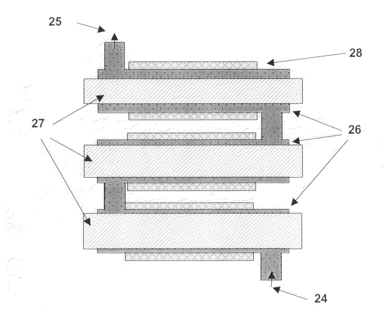
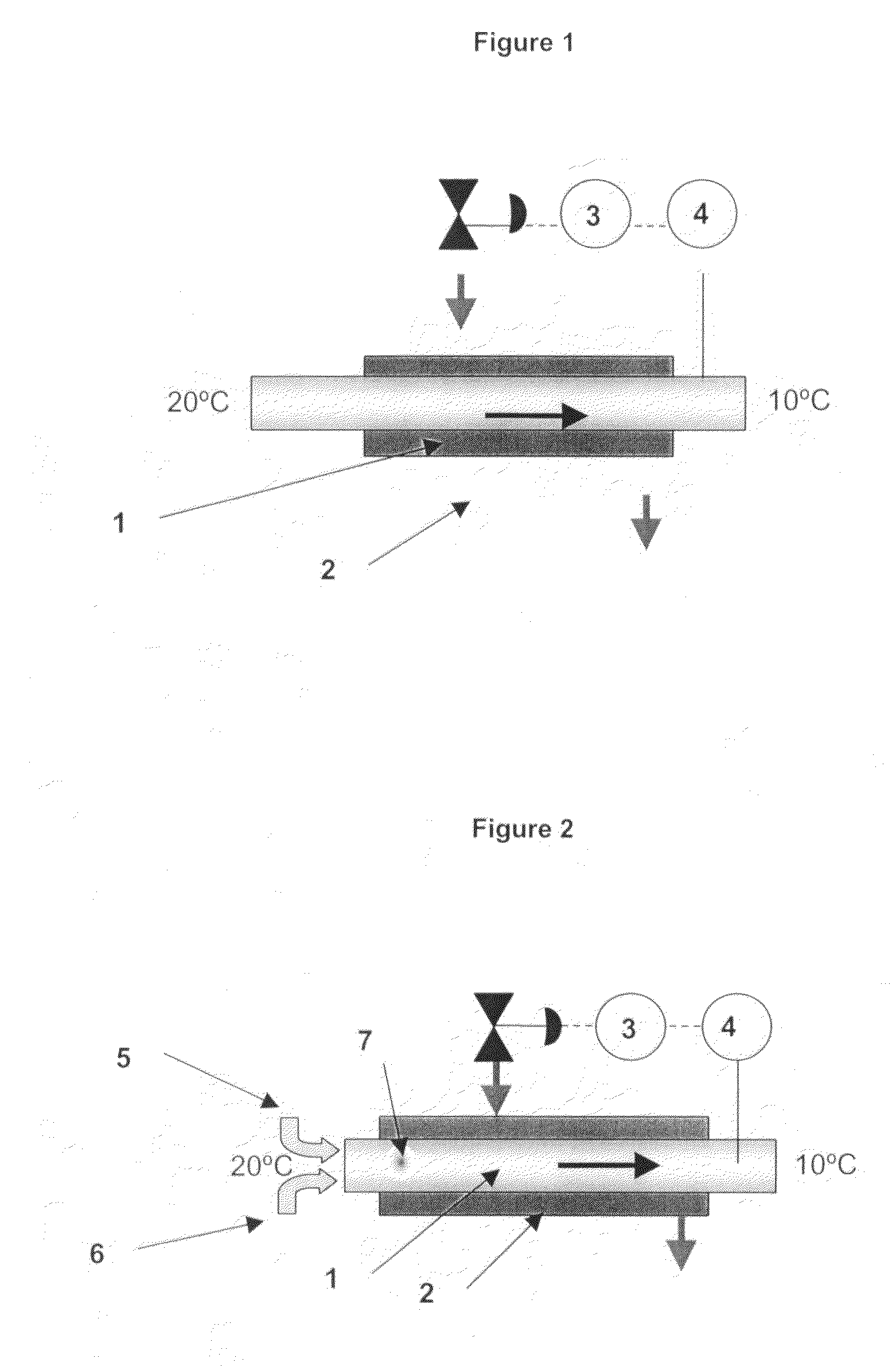
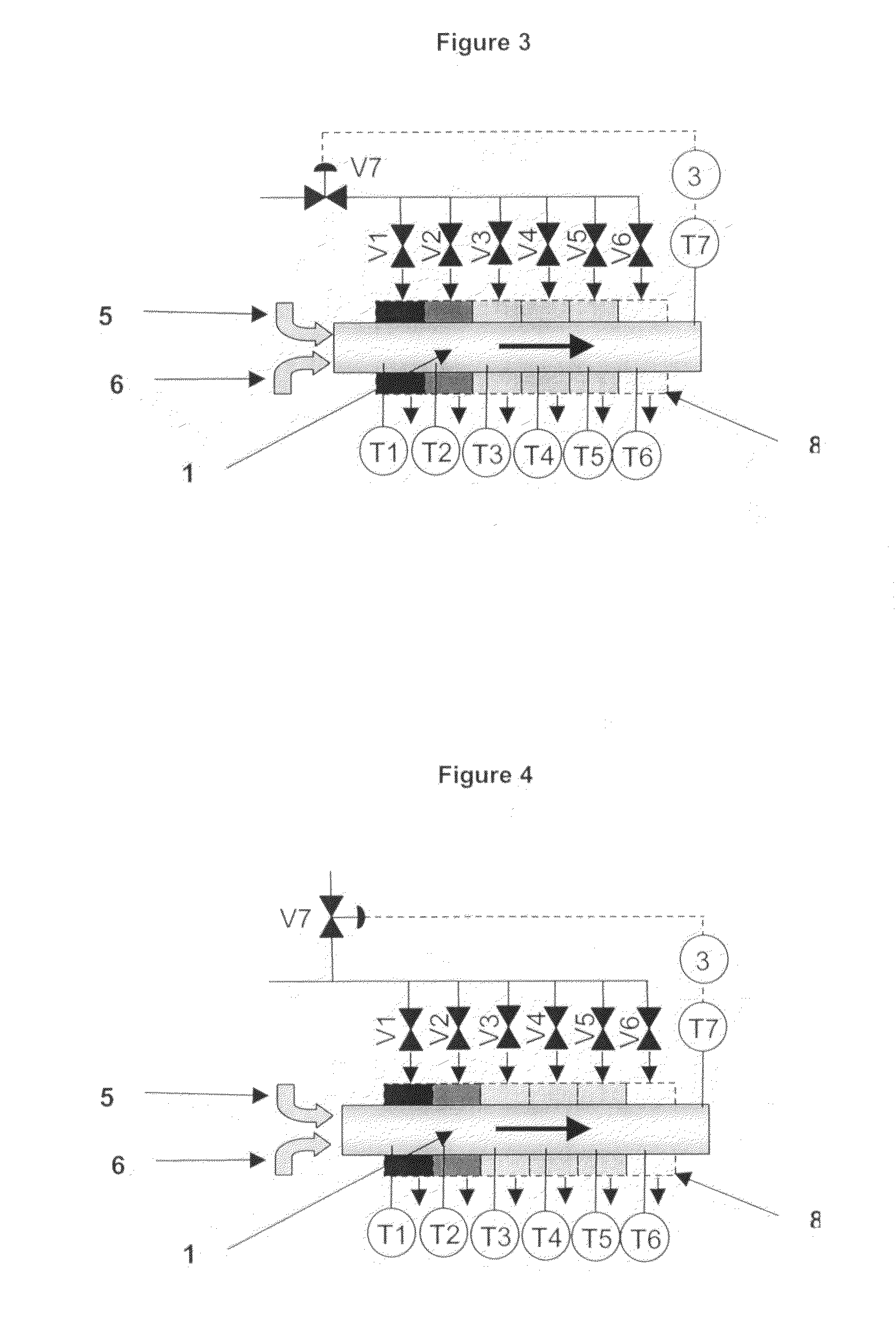
[0032]The present disclosure provides a design of plate heat exchanger which gives the user complete freedom to select plate spacing (both uniform and non-uniform plate spacing). It also has separate heat transfer fluid supplies to each plate and where necessary, the process material can be piped into or out of any plate. It also has design features that permit the user to fit a variety of instruments or fittings to each plate. This gives it superior capabilities to traditional heat exchangers and makes it an ideal design for use as a “variable volume” and / or “variable heat flux heat exchanger”.

Problems solved by technology

However, for many reasons the traditional plate heat exchanger does not lend itself to the concepts of ‘variable volume’ or ‘variable heat flux’.

Method used


Image

  • Variable plate heat exchangers
  • Variable plate heat exchangers
  • Variable plate heat exchangers

Examples


Embodiment Construction

The Variable Plate Heat Exchanger

[0056]The considerations and solutions for this new variable plate design are discussed in the section below.

(a) Variable Plate—Variable Volume

[0057]Traditional plate heat exchangers are made up with plate packs where the individual plates in a given plate pack have common plate spacings (although several different types of plate pack may be fitted within the same heat exchanger frame).[0058]The preferred design of the present disclosure uses a plate pack which has two or more different plate spacings within it. Also the process conduit can pass directly though the heat transfer plate and, if necessary, this can be achieved without welds or seals on the inter plate conduit. Alternatively, the process conduit can be diverted into or out of the plate at any point in the plate stack. Also the heat transfer fluid conduit can be fed to each plate from the outside and does not need to pass through a space which is sealed from but surrounded by process mate...


PUM


Abstract

A heat exchanger is provided which is capable of sophisticated operations such as undertaking chemical reactions, where particular velocity profiles are required or unusual heat transfer profiles are needed and comprises a unitary heat exchanger comprising a plurality of distinct heat transfer elements or zones containing heat transfer fluid through which a process material flows wherein heat transfer fluid is delivered and removed separately to each heat transfer element or zone.

Description

BACKGROUND[0001]1. Field of the Disclosure[0002]This present disclosure relates to plate heat exchangers where the process material flows over the plate surfaces.[0003]The underlying purpose of this design is to build a heat exchanger which is capable of more sophisticated operations such as undertaking chemical reactions, where particular velocity profiles are required or unusual heat transfer profiles are needed. Some of the functional requirements of this heat exchanger are:[0004]The option of a heat transfer surface which is made up of multiple heat transfer elements these can be set or controlled independently.[0005]The option of multiple stages with variable plate spacing.[0006]The option of fitting instruments and fittings at different points within the process conduit.[0007]The option of injecting or removing the process material from any plate.[0008]The option of opening up the process conduits for cleaning or modification.[0009]A design of heat exchanger which embodies the...

Claims


Application Information

Patent Timeline
IPC IPC(8): B01J19/00F28F7/00B01J19/24F28D9/00F28F13/08F28F27/02
CPCB01J19/249F28F27/02B01J2208/00212B01J2208/00221B01J2208/0053B01J2208/021B01J2208/022B01J2219/00085B01J2219/00094B01J2219/00159B01J2219/2453B01J2219/2458B01J2219/2462B01J2219/2464B01J2219/2479B01J2219/2481B01J2219/2485B01J2219/2493B01J2219/2495B01J2219/2498F28D9/00F28F13/08B01J2208/0015
Inventor ASHE, ROBERT
Owner ASHE MORRIS LTD
Learn More