Support assembly connectable to a base structure

Inactive Publication Date: 2009-04-09
WAINLAND ROBERT ANDREW
View PDF22 Cites 7 Cited by
  • Summary
  • Abstract
  • Description
  • Claims
  • Application Information

AI Technical Summary

Benefits of technology

[0015]Moreover, the attachment mechanism may further include a tightening assembly. Specifically, the tightening assembly may comprise a fastener that may either penetrate the surface of the base structure or provide an engagement therewith at least partially solely on the basis of pressure and friction. Either way, the fastener may be at least partially manipulated by hand, which may preferably be structured to minimize or completely eliminate the need for tools or other external devices to facilitate the tightening or loosening thereof. As such, the fastener may include a thumb screw or an equivalent structure. In addition, however, the fastener may include a conventional type screw which may require the utilization of a screw driver or other like tool to tighten or loosen.
[0018]The lower surface of the overlying member in at least one preferred embodiment of the present invention may be structured to define at least one or a plurality of receiving slots thereon. The receiving slots may be cooperatively structured such that the protruding portions of the mounting devices may be removably disposed therein. Further, the receiving slots may be structured to have a dimension slightly larger than that of the protruding portions of the mounting devices. More in particular, the length, width, and / or depth of the receiving slots may be larger, albeit only minimally, so as to allow some movement and / or adjustment of the overlying member(s) or mounting device(s).
[0019]Moreover, at least one alternate embodiment of the present invention may further include a substantially “reversed” configuration wherein the overlying member includes at least one or a plurality of protruding portions, for example, tabs disposed on or along the lower surface thereof. The protruding portions may be located substantially near the edges of the overlying member or closer to the center thereof. Additionally, the mounting devices of the “reversed” embodiment of the present invention may be structured to define at least one or a plurality of receiving slots cooperatively structured and dimensioned such that the protruding portions of the overlying member may be removably insertable therein.
[0020]Additionally, in at least one embodiment of the present invention, the mounting device may be dimensioned and configured to dispose the panel member above and / or in outwardly spaced relation from the base to facilitate the placement of pipes, wiring, and other utilitarian devices between the base and corresponding panel. More in particular, the support assembly may be structured to have a height such that when the support assembly of the present invention is completely assembled and operatively disposed on the base structure, the distance between the base structure and the overlying member defines an opening therethrough. The opening may be of a sufficient dimension to allow pipes, wiring, and other like devices and structures to pass through unobstructed by the support assembly of the present invention.

Problems solved by technology

Unfortunately, however, the typically structured attic is not designed or even capable of supporting heavy loads exerted from, for example, storage boxes,. bags, carts, trunks, and / or individuals crawling, walking, or standing thereon.
Specifically, the ceiling tile will typically crack or break when such a load is exerted thereon.
Thus, the large, at least partially open areas provided by most attics are not being utilized to their fullest potential, if at all.

Method used


Image

  • Support assembly connectable to a base structure
  • Support assembly connectable to a base structure
  • Support assembly connectable to a base structure

Examples


Embodiment Construction

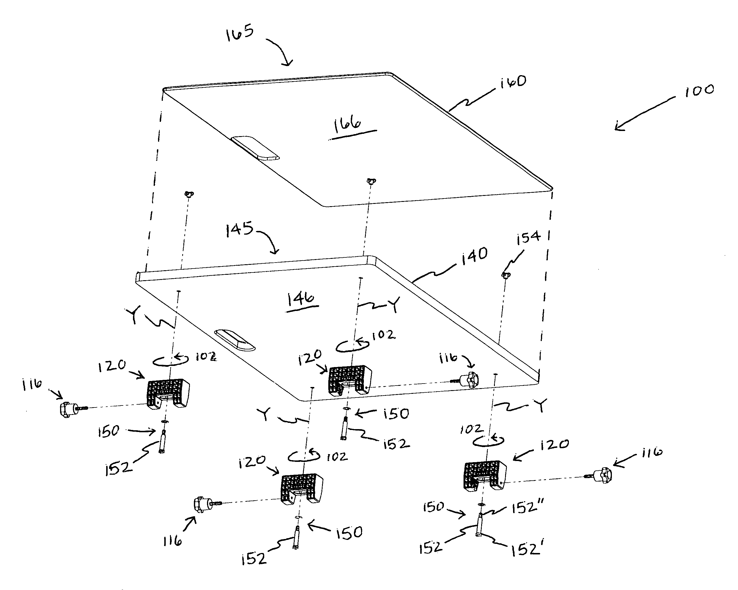
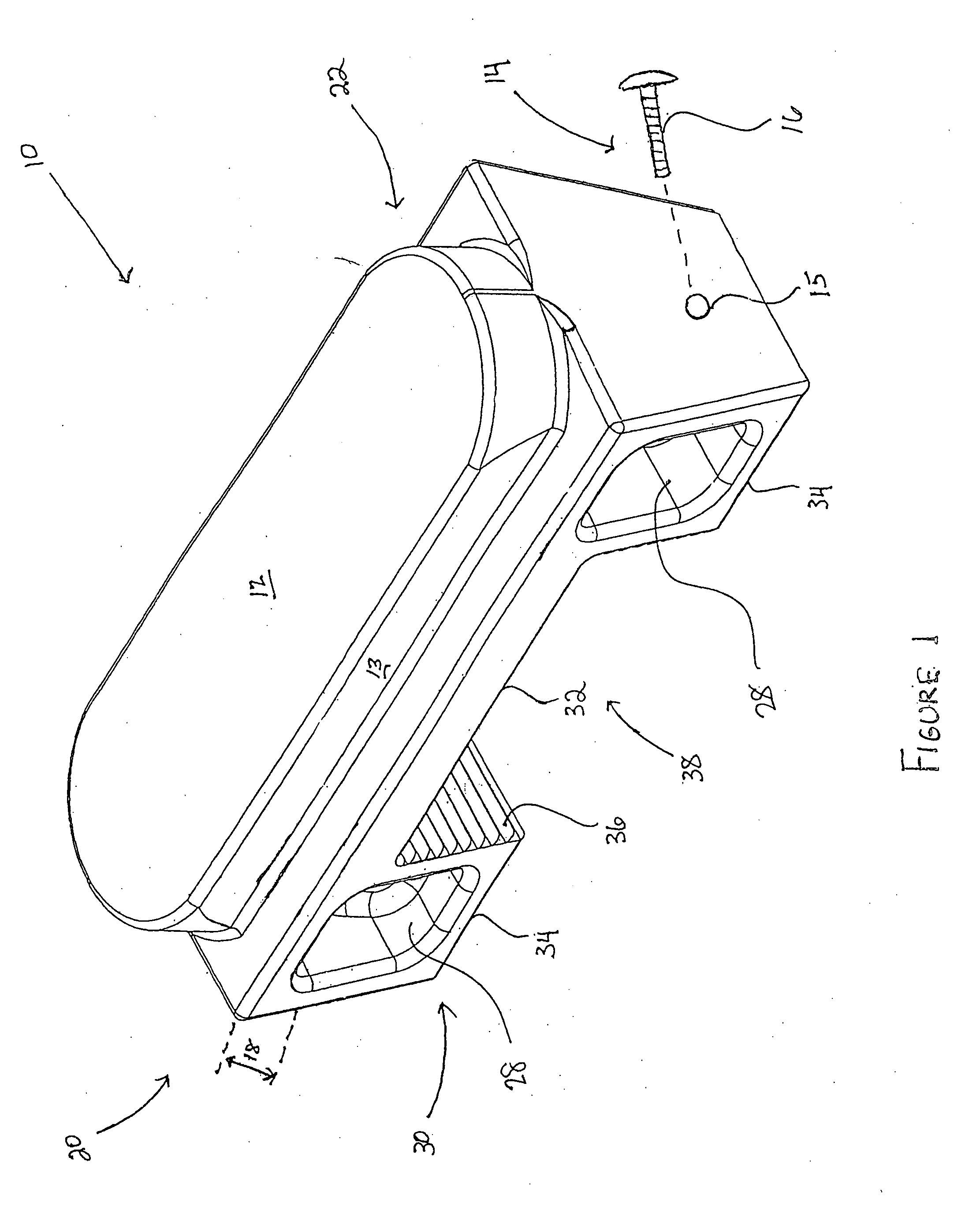
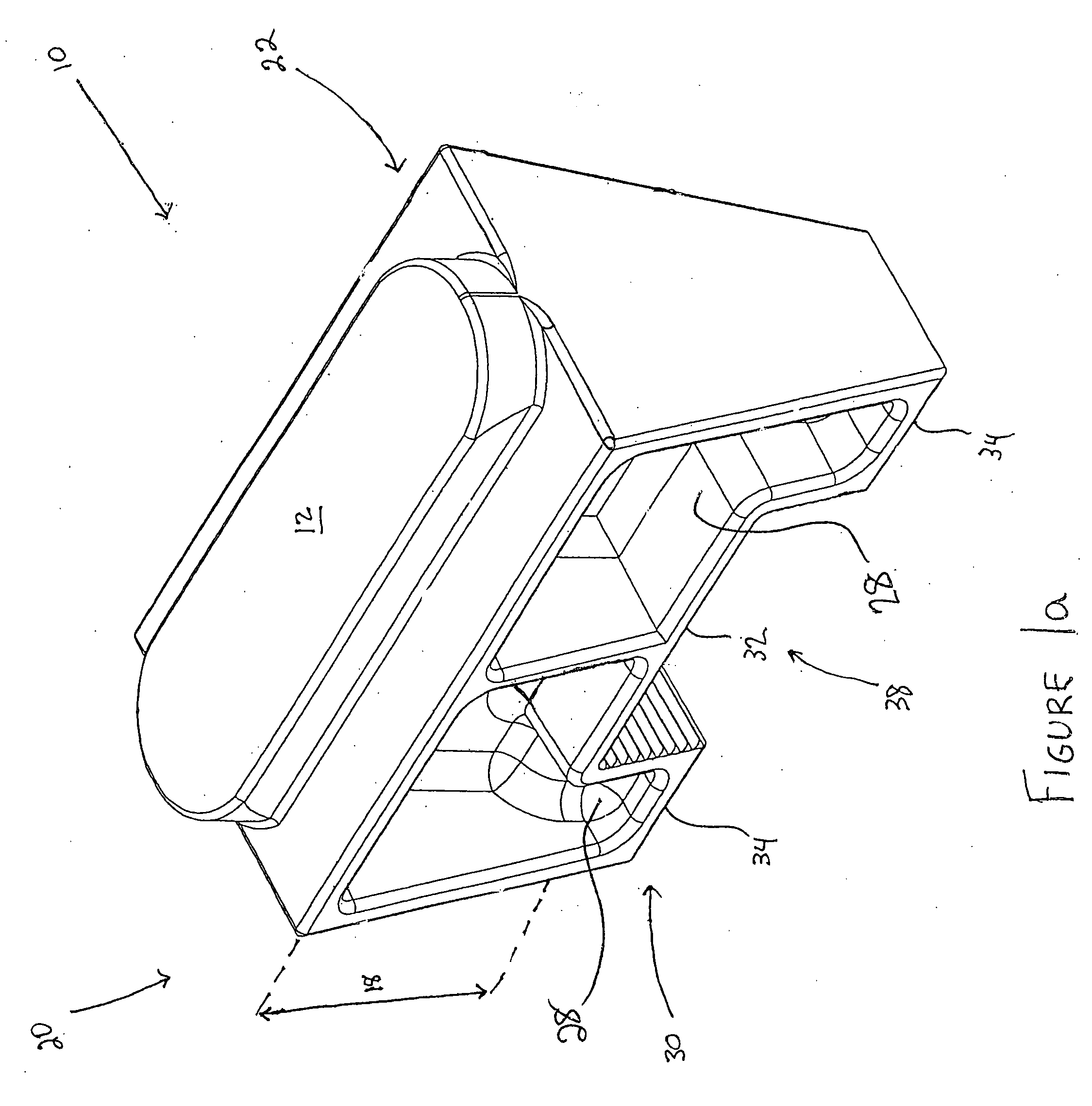
[0045]As shown in the accompanying drawings, the present invention is directed to a support assembly, generally indicated as 10, which is connectable to a base structure 50. The base structure 50 may include a beam, joist, or any portion of a truss, including but not limited to the top chord, bottom chord, and / or web. In addition, the base structure 50 may include any other structure preferably located in an attic of a house, apartment, or other dwelling, building, or structure. The base 50, however, is in no way limited to structures disposed in such locations. Accordingly, the base structure 50 may be vertically oriented, as in a wall, or disposed in any other conceivable angle. Additionally, the base structure 50 may be disposed at any height or elevation, for example, near a ceiling or roof of a house, building, etc.

[0046]As such, the support assembly 10 of the present invention is versatile in that it may be utilized to fit a plurality of needs or circumstances, including, for ...


PUM


Abstract

A support assembly connectable to a base structure preferably disposed in an attic or other like location of a house, dwelling, and / or other building to provide or facilitate storage and or standing, walking, or crawling thereon. The support assembly comprising at least one or a plurality of mounting devices and at least one panel member having an upper surface and a lower surface. The support assembly further comprising at least one anchoring assembly structured to connect the mounting device to the panel member such that the mounting device is disposable in a plurality of orientations relative to the panel member.

Description

BACKGROUND OF THE INVENTION[0001]1. Field of the Invention[0002]This invention relates to a support assembly connected to a base structure preferably disposed in an attic or other like location of a house, dwelling, building, or other structure. As such, the support assembly may operatively provide or facilitate storage space and / or any other flooring, or covering structure. The support assembly may include at least one or a plurality of mounting devices and at least one or a plurality of overlying members or panel members. In addition, the mounting devices may include an attachment mechanism structured to be removably connectable to the base structure.[0003]2. Description of the Related Art[0004]Many buildings, houses, and other like structures include accessible attic compartments between the inner ceiling and roof, which typically yield a large, at least partially open area. Furthermore, the floors of many of the attics today include a plurality of spaces, which may or may not be...

Claims


Application Information

Patent Timeline
IPC IPC(8): A47B91/08
CPCF16B5/0216
Inventor WAINLAND, ROBERT ANDREW
Owner WAINLAND ROBERT ANDREW
Why Eureka
Try Eureka