Heating System

a heating system and boiler technology, applied in the field of heating systems, can solve the problems of inefficiency of large boilers with large heat output, small boilers with relatively small heat outputs, and inability to adequately supply the heating needs of large buildings, so as to reduce the amount of heat that needs to be imparted by boilers, work less hard, and fuel consumption.

Inactive Publication Date: 2009-04-09
CANETIS HLDG LTD
View PDF43 Cites 17 Cited by
  • Summary
  • Abstract
  • Description
  • Claims
  • Application Information

AI Technical Summary

Benefits of technology

[0004]Preferably the primary heat exchanger comprises at least one heat exchange pipe closely coupled with a plurality of burners and a portion of the heat exchange pipe passes between two or more of the burners such that the heat exchange pipe receives heat from both sides. This scheme improves heat delivery into the heat exchange pipe allowing the combined burner and heat exchanger combination to be physically smaller than prior burner and heat exchanger combinations for the same “power output”. The provision of multiple burners also allows the range of modulation of the boiler output to be varied over a greater range. Modulators allow the amount of gas admitted into the manifold to be varied. Typically a modulator has a 3 to 1 or 4 to 1 modulation ratio. Thus a boiler having a 30 kW rate can be run down to around an 8 kW minimum. However, if the burners have been sub-divided into small burners, then some of them can be switched off altogether. So, using the same modulator, if four burners are provided then the boiler can be modulated down to 2 kW. Also modulators need not be provided for every burner as two or three burners can be used in an on or off mode with fine control being provided via the or each burner having a modulator.

Problems solved by technology

It can intuitively be seen that a large boiler has a large “thermal mass” so using a large boiler having a large heat output would be inefficient if only a small heating load is to be serviced.
Similarly a small boiler having a relatively small heat output wont be able to adequately supply the heating needs of a large building.

Method used


Image

  • Heating System
  • Heating System
  • Heating System

Examples


Embodiment Construction

[0023]There is a general desire to achieve boilers, whether domestic or industrial, that occupy as small a space as reasonably possible whilst maintaining efficiency. Additionally users want heat output, for example to provide hot water for washing, quickly.

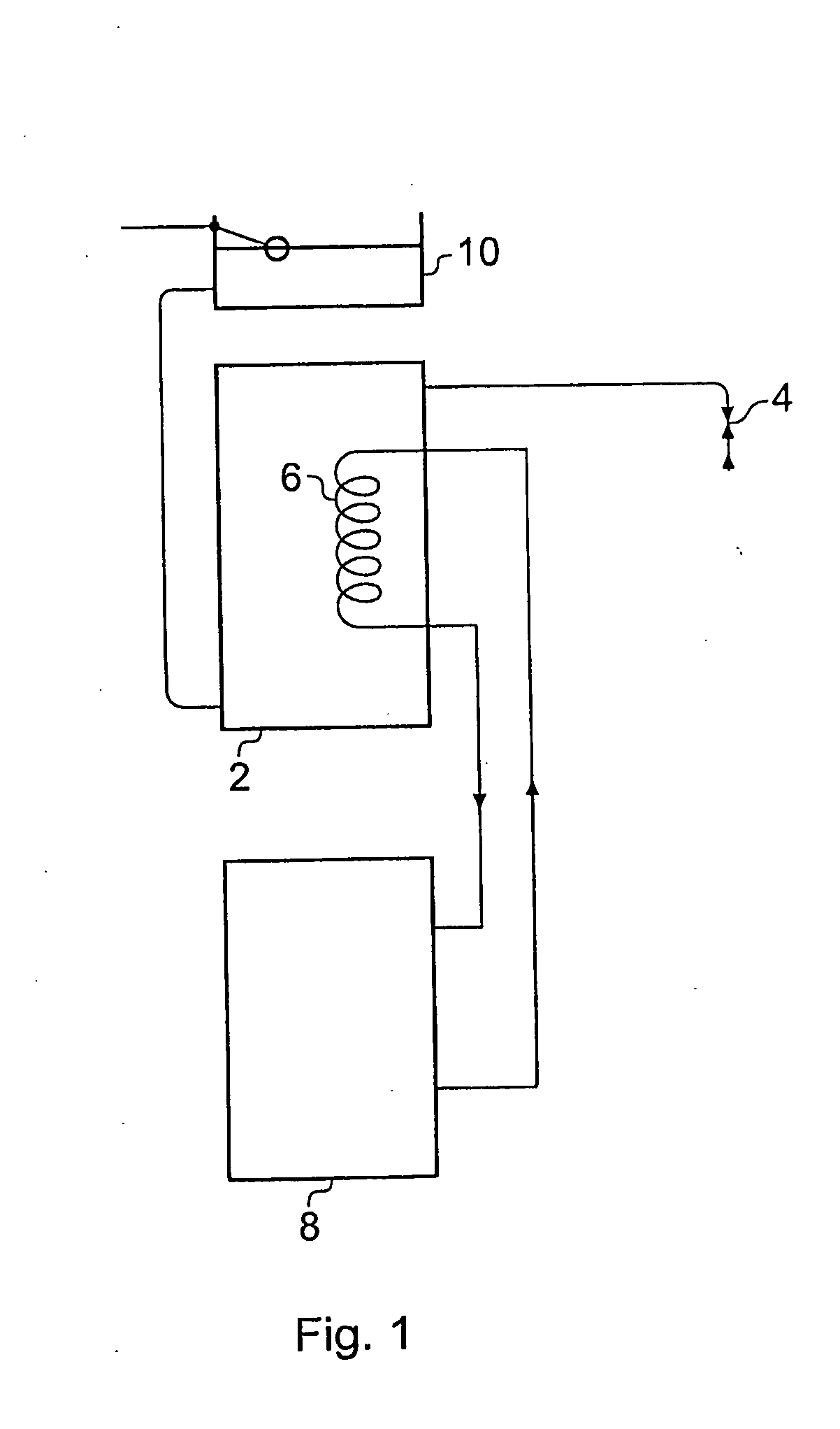
[0024]One solution to providing hot water quickly was to provide a tank which held water that had been warmed to a desired hot water output temperature. Thus, as shown in FIG. 1 a storage tank 2 was connected so as to deliver warmed water form an upper region of the tank, for example, for running a bath. The tank 2 has a heater or heat exchanger therein such that the water can be warned to a desired temperature for use. In this example a heat exchanger 6 is warmed by a fuel burning boiler 8. Water is admitted into the tank 2 via a header tank 10.

[0025]This solution to providing hot water has several drawbacks.[0026]1) The tank looses heat—so the water requires periodic heating even if no water is drawn from the tank. This is inef...


PUM


Abstract

A heating system comprising a fuel burner in co-operation with a primary heat exchanger, a reservoir for storing warmed water in, and a blending valve, and a controller wherein in use a user can signal to the controller to warm the water in the water store using a heater or by the primary heat exchanger, and when hot water is required water is removed from the water store and mixed with water from a cold main prior to being or after the water from the cold main has been admitted to a further heat exchanger for heating the water.

Description

FIELD OF THE INVENTION[0001]The present invention relates to a heating system.BACKGROUND OF THE INVENTION[0002]Boilers are routinely provided for producing hot water for washing and bathing, and also for supply to space heating systems, such as radiators or under floor heating. Within a boiler a fuel is combusted to generate hot gas and this gas passes over or around a heat exchanger in order to warm a liquid, often water, within the heat exchanger. A boiler is designed for an expected heat output. It can intuitively be seen that a large boiler has a large “thermal mass” so using a large boiler having a large heat output would be inefficient if only a small heating load is to be serviced. Similarly a small boiler having a relatively small heat output wont be able to adequately supply the heating needs of a large building.SUMMARY OF THE INVENTION[0003]According to a first aspect of the present invention there is provided a heating system comprising a fuel burner in co-operation with ...

Claims


Application Information

Patent Timeline
Patent Type & Authority Applications(United States)
IPC IPC(8): F24D3/08F24H1/48F24H8/00
CPCF24D3/08F24D2200/14F24H1/34F24H1/41Y02B30/102F24H1/52F24H8/00Y02B10/20F24H1/50Y02B30/00F24D3/082F24D19/1066F24D19/1069F24H1/46
Inventor FARRELL, CHRISTOPHER C.
Owner CANETIS HLDG LTD
Why Eureka
Try Eureka