Engine blow-by gas returning apparatus

a technology of blowing gas and return passage, which is applied in the direction of combustion engines, machines/engines, crankcase ventillation, etc., can solve the problems of damage to the valve element of the pcv valve and the crankcase, high-pressure gas flows back in the return passage to flow in the pcv valve,

Inactive Publication Date: 2009-04-09
AISAN IND CO LTD
View PDF4 Cites 57 Cited by
  • Summary
  • Abstract
  • Description
  • Claims
  • Application Information

AI Technical Summary

Benefits of technology

[0009]The present invention has been made in view of the above circumstances and has an object to provide an engine blow-by gas returning apparatus capable of protecting a PCV valve or a crank case from excessive pressure rise even when the pressure in an intake passage suddenly rises and acts on a returning passage.

Problems solved by technology

In the case where the technique disclosed in JP '222A is applied to an engine with a supercharger as mentioned in JP '556U, JP '532A, and JP '514U, there is a risk that high-pressure gas flows back in the returning passage to flow in the PCV valve when the pressure in the intake passage suddenly rises due to supercharged air by the supercharger or backfire.
Accordingly, the back-flow of the high-pressure gas in the PCV valve may cause damage to a valve element of the PCV valve and the crank case.

Method used


Image

  • Engine blow-by gas returning apparatus
  • Engine blow-by gas returning apparatus
  • Engine blow-by gas returning apparatus

Examples


first embodiment

[0027]A detailed description of a first preferred embodiment of an engine blow-by gas returning apparatus embodying the present invention will now be given referring to the accompanying drawings.

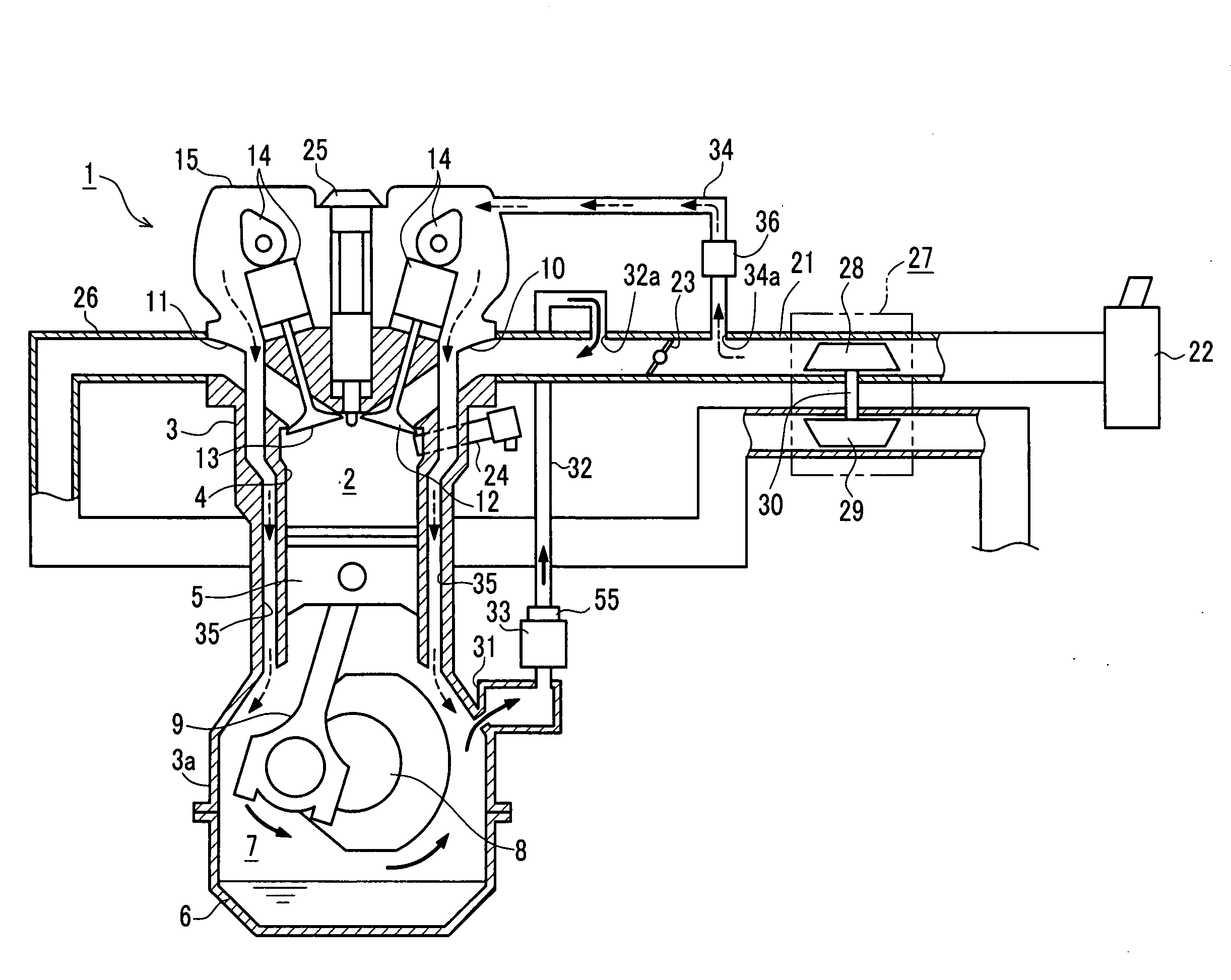
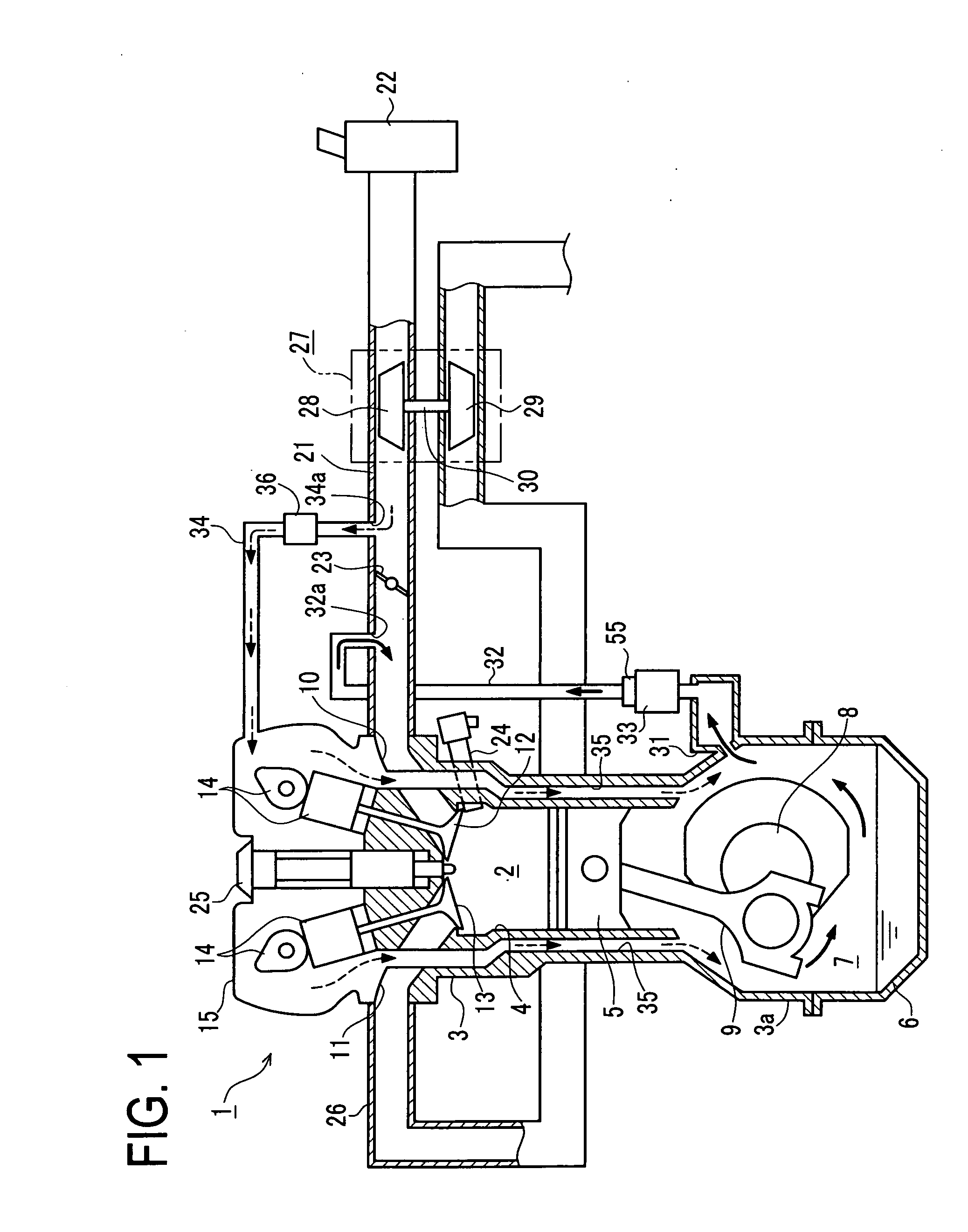
[0028]FIG. 1 is a schematic configuration view of a gasoline engine system including a blow-by gas returning apparatus in this embodiment. An engine 1 constituting this engine system is a multiple-cylinder ignition engine of a direct injection type arranged to directly inject fuel into a combustion chamber 2. An engine block 3 constituting the engine 1 is formed with a plurality of cylinder bores 4 in each of which a piston 5 is provided to be vertically movable. A lower part of the engine block 3 is provided with a crank case 3a, which is assembled with an oil pan 6. Those crank case 3a and oil pan 6 form a crank chamber 7. In this crank chamber 7, a crank shaft 8 is rotatably supported and coupled to each piston 5 through each connecting rod 9.

[0029]The combustion chamber 2 formed above th...

second embodiment

[0041]A second embodiment of an engine blow-by gas returning apparatus according to the present invention will be described referring to the accompanying drawing.

[0042]In each subsequent embodiment, the same or similar components as those in the first embodiment are given the same reference signs and their details are not omitted. The following explanation will be made with a focus on differences from the first embodiment.

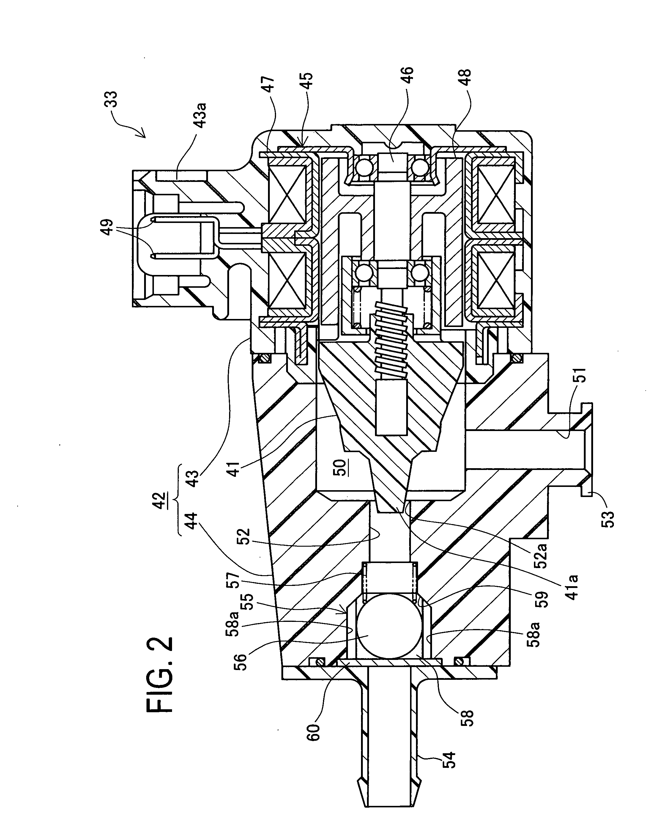
[0043]FIG. 3 is a sectional view of a PCV valve 61 in the second embodiment. The blow-by gas returning apparatus in this embodiment differs from the first embodiment in a configuration of the PCV valve 61. Specifically, this PCV valve 61 differs from that in the first embodiment in the shape of the sub housing 44 and the placement of the check valve 55. The sub housing 44 is formed to be axially shorter than that in the first embodiment. In the second embodiment, the check valve 55 is placed in the inlet port 51. This check valve 55 is identical in structure to tha...

third embodiment

[0045]A third embodiment of an engine blow-by gas returning apparatus according to the present invention will be described referring to the accompanying drawing.

[0046]FIG. 4 is a schematic configuration view of a gasoline engine system including a blow-by gas returning apparatus in the third embodiment. FIG. 5 is a sectional view of a first PCV valve 62 in the third embodiment. This embodiment differs from the aforementioned embodiments in a passage configuration of the blow-by gas returning apparatus, a configuration of the first PCV valve 62, and others. Specifically, as shown in FIG. 4, the blow-by gas returning apparatus is further provided with a second returning passage 63 and the second PCV valve 64. The second PCV valve 64 is provided integral with the first PCV valve 62. The second returning passage 63 is disposed so that one end connected with the second PCV valve 64 and the other end communicating with the intake passage 21 upstream of the supercharger 27. As shown in FIG...


PUM


Abstract

A blow-by gas returning apparatus is arranged to allow blow-by gas leaking from a combustion chamber of an engine into a crank chamber to flow in an intake passage through a returning passage, and to regulate a flow rate of the blow-by gas by a PCV valve placed in the returning passage. A supercharger is placed in the intake passage. The PCV valve is adapted to change a position of the valve element by electromagnetic force to change a passage opening area. A check valve is placed integral with the PCV valve in the returning passage between the valve element of the PCV valve and the intake passage. The check valve is arranged to inhibit back-flow of the gas from the intake passage.

Description

BACKGROUND OF THE INVENTION[0001]1. Field of the Invention[0002]The present invention relates to an engine blow-by gas returning apparatus arranged to cause blow-by gas leaking from a combustion chamber of an engine into a crank case to flow in an intake system of the engine and then return to the combustion chamber.[0003]2. Description of Related Art[0004]Heretofore, there have been known some techniques of this type disclosed in JP8 (1996)-338222A, JP56 (1981)-129556U, JP2003-184532A, and JP62 (1987)-150514U. In particular, JP '222A discloses that a flow rate of blow-by gas in a returning passage is regulated by an electromagnetically driven PCV valve.[0005]On the other hand, JP '556U discloses a blow-by gas processing apparatus provided for an engine with a supercharger and provided with a first returning passage for allowing blow-by gas to flow from an engine body to an intake passage upstream of the supercharger and a second returning passage for allowing blow-by gas to flow fr...

Claims


Application Information

Patent Timeline
Patent Type & Authority Applications(United States)
IPC IPC(8): F02B25/06
CPCF01M13/022F01M2013/027F01M13/028
Inventor ASANUMA, HIROSHISUZUKI, KOICHIISHIDA, KATSUMI
Owner AISAN IND CO LTD
Why Eureka
Try Eureka