Automated directional drilling apparatus and methods

a directional drilling and automatic technology, applied in the direction of directional drilling, borehole/well accessories, surveys, etc., can solve the problems of not being able to provide directional drillers with feedback, drillers cannot rely on the most recent survey data to accurately assess the progress or effectiveness of operations, and drillers cannot utilize the most recent survey data to assess effectiveness or accuracy

Active Publication Date: 2009-04-09
NABORS DRILLING TECH USA INC
View PDF72 Cites 385 Cited by
  • Summary
  • Abstract
  • Description
  • Claims
  • Application Information

AI Technical Summary

Benefits of technology

[0016]In another exemplary aspect, the present disclosure is directed to a system for drilling to a target location. The system includes a receiving device adapted to receive an input comprising a planned drilling path to a target location, a sensory device adapted to determine a projected location of a bottom hole assembly of a drilling system, and a logic device adapted to compare the projected location of the bottom hole assembly to the planned drilling path to determine a deviation amount from the planned path. The second logic device is adapted to create a modified drilling path to the target location as selected based on the amount of deviation from the planned drilling path. A drilling rig control signal generator is adapted to automatically and electronically generate one or more drilling rig control signals at the surface of the well that steer the bottom hole assembly of the drilling system to the target location along the modified drilling path.
[0017]In one aspect, the system includes a drawworks drive, a top drive, and a mudpump. The control signal generator transmits the one or more signals to control the drawworks, the top drive, and the mudpump to change a direction of the bottom hole assembly as drilling proceeds. In one aspect, the second logic device creates a modified drilling path based upon whether the amount of deviation from the planned path exceeds a threshold. It includes means for creating a modified drilling path that intersects the planned drilling path if the amount of deviation from the planned path exceeds a first threshold amount of deviation from the planned path and means for creating a modified drilling path that does not intersect the planned drilling path if the amount of deviation from the planned path exceeds a second threshold amount of deviation from the planned path.
[0018]In another exemplary aspect, the present disclosure is directed to a method of directionally steering a bottom hole assembly during a drilling operation from a drilling rig to an underground target location. The method includes the steps of: generating a drilling plan having a drilling path and an acceptable margin of error as a tolerance zone; receiving data indicative of one or more directional trends and a projection to bit depth; determining the actual location of the bottom hole assembly based on the one or more directional trends and the projection to bit depth; and determining whether the bit is within the tolerance zone. The method also includes comparing the actual location of the bottom hole assembly to the planned drilling path to identify an amount of deviation from the planned path of the bottom hole assembly from the actual drilling path and creating a modified drilling path based on the amount of deviation from the planned path. This includes creating a modified drilling path that intersects the planned drilling path if the amount of deviation from the planned path exceeds a first threshold amount of deviation from the planned path, and creating a modified drilling path to the target location that does not intersect the planned drilling path if the amount of deviation from the planned path exceeds a second threshold amount of deviation from the planned path. The method further includes determining a desired tool face orientation to steer the bottom hole assembly along the modified drilling path; automatically and electronically generating one or more drilling rig control signals at the well surface at a directional steering controller; and outputting the one or more drilling rig control signals to a drawworks and a top drive to steer the bottom hole assembly along the modified drilling path.

Problems solved by technology

However, if directional drilling operations call for one or more transitions between sliding and rotating within the span of a single drill pipe joint or connection, the driller cannot rely on the most recent survey to accurately assess the progress or effectiveness of the operation.
For example, the driller cannot utilize the most recent survey data to assess the effectiveness or accuracy of a “slide” that is initiated after the survey was obtained.
The conventional use of surveys does not provide the directional driller with any feedback on the progress or effectiveness of operations that are performed after the most recent survey measurements are obtained.
This can be difficult, time consuming, and complex.
Thus, reorienting the toolface in a bore is very complex, labor intensive, and often inaccurate.

Method used


Image

  • Automated directional drilling apparatus and methods
  • Automated directional drilling apparatus and methods
  • Automated directional drilling apparatus and methods

Examples


Embodiment Construction

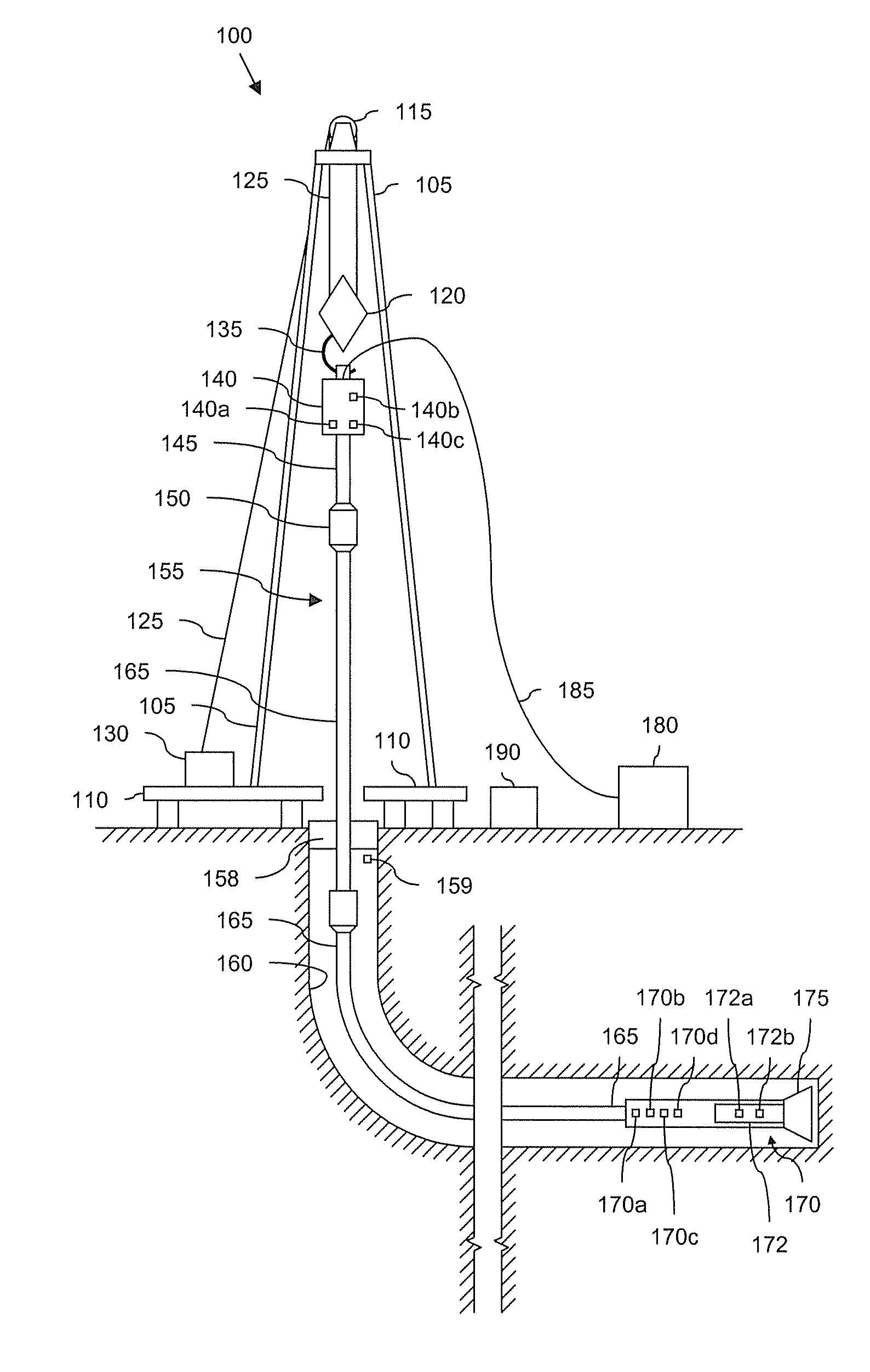
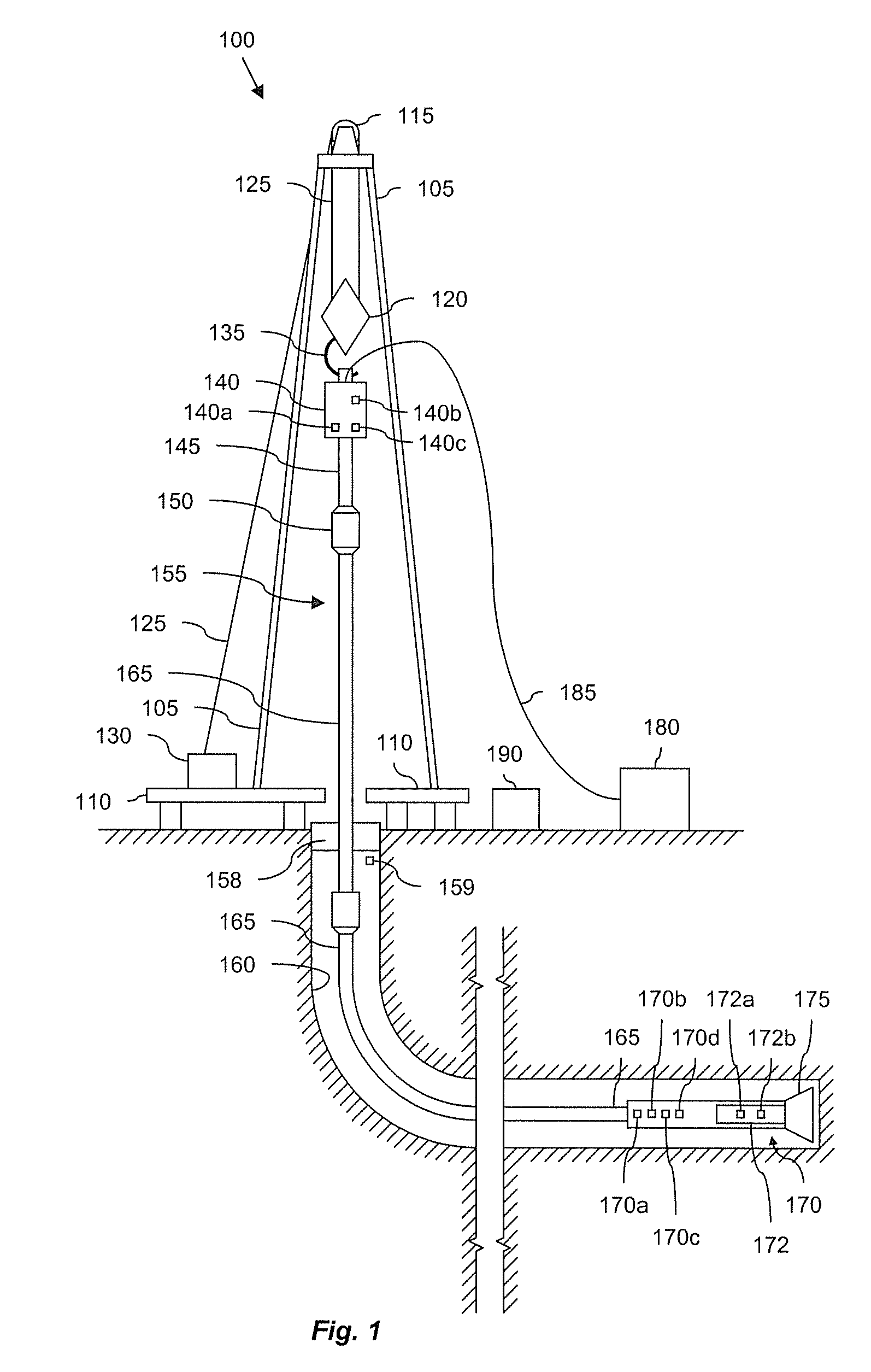
[0035]It is to be understood that the present disclosure provides many different embodiments, or examples, for implementing different features of various embodiments. Specific examples of components and arrangements are described below to simplify the present disclosure. These are, of course, merely examples and are not intended to be limiting. In addition, the present disclosure may repeat reference numerals and / or letters in the various examples. This repetition is for the purpose of simplicity and clarity and does not in itself dictate a relationship between the various embodiments and / or configurations discussed. Moreover, the formation of a first feature over or on a second feature in the description that follows may include embodiments in which the first and second features are formed in direct contact, and may also include embodiments in which additional features may be formed interposing the first and second features, such that the first and second features may not be in dir...


PUM


Abstract

Methods and systems for drilling to a target location include a control system that receives an input comprising a planned drilling path to a target location and determines a projected location of a bottom hole assembly of a drilling system. The projected location of the bottom hole assembly is compared to the planned drilling path to determine a deviation amount. A modified drilling path is created to the target location as selected based on the amount of deviation from the planned drilling path, and drilling rig control signals that steer the bottom hole assembly of the drilling system to the target location along the modified drilling path are generated.

Description

CROSS-REFERENCE TO RELATED APPLICATIONS[0001]This application claims the benefit of: (1) U.S. Provisional Patent Application No. 60 / 985,869, filed Nov. 6, 2007, now pending (Attorney Docket No. 38496.45); (2) U.S. Provisional Patent Application No. 61 / 016,093, filed Dec. 21, 2007, now pending (Attorney Docket No. 38496.43); and (3) U.S. Provisional Patent Application No. 61 / 026,323, filed Feb. 5, 2008, now pending (Attorney Docket No. 38496.46). This application is also: (4) a continuation-in-part of U.S. patent application Ser. No. 11 / 859,378, filed Sep. 21, 2007, now pending (Attorney Docket No. 38296.12); (5) a continuation-in-part of U.S. patent application Ser. No. 11 / 952,511, filed Dec. 12, 2007, now pending (Attorney Docket No. 38296.19), which claims the benefit of U.S. Provisional Patent Application No. 60 / 869,047, filed Dec. 7, 2006, now expired (Attorney Docket No. 38496.13); (6) a continuation-in-part of U.S. patent application Ser. No. 11 / 847,048, filed Aug. 29, 2007, n...

Claims


Application Information

Patent Timeline
Patent Type & Authority Applications(United States)
IPC IPC(8): E21B7/06E21B44/02G06F19/00
CPCE21B7/04E21B44/02
Inventor BOONE, SCOTT GILBERTELLIS, BRIANGILLAN, COLINKUTTEL, BEAT
Owner NABORS DRILLING TECH USA INC
Why Eureka
Try Eureka