Heating resistance element component and thermal printer

a technology of heating resistors and components, applied in the field of heating resistor components and thermal printers, can solve the problems of reducing heating efficiency and difficulty in obtaining a sufficient strength to the external load, and achieve the effects of reducing power consumption, preventing heat generation in the heating resistor, and increasing the heating efficiency of the heating resistor

Inactive Publication Date: 2009-04-09
SEIKO INSTR INC
View PDF2 Cites 10 Cited by
  • Summary
  • Abstract
  • Description
  • Claims
  • Application Information

AI Technical Summary

Benefits of technology

[0008]The present invention has been made in view of the aforementioned circumstances, and an object thereof is to provide a heating resistance element component capable of increasing heating efficiency of a heating resistor to reduce power consumption and increasing a strength of a substrate under the heating resistor, and a thermal printer.

Problems solved by technology

However, in the thermal head disclosed in JP 2004-34601 A, heat generated in a heating element passes through a reinforcement layer, an undercoat, and a heat storage layer at a connecting portion to be diffused to an entire substrate, which leads to a decrease in heating efficiency.
However, the reinforcement layer has a bending portion, which makes it difficult to obtain a sufficient strength to the external load.

Method used


Image

  • Heating resistance element component and thermal printer
  • Heating resistance element component and thermal printer
  • Heating resistance element component and thermal printer

Examples


first embodiment

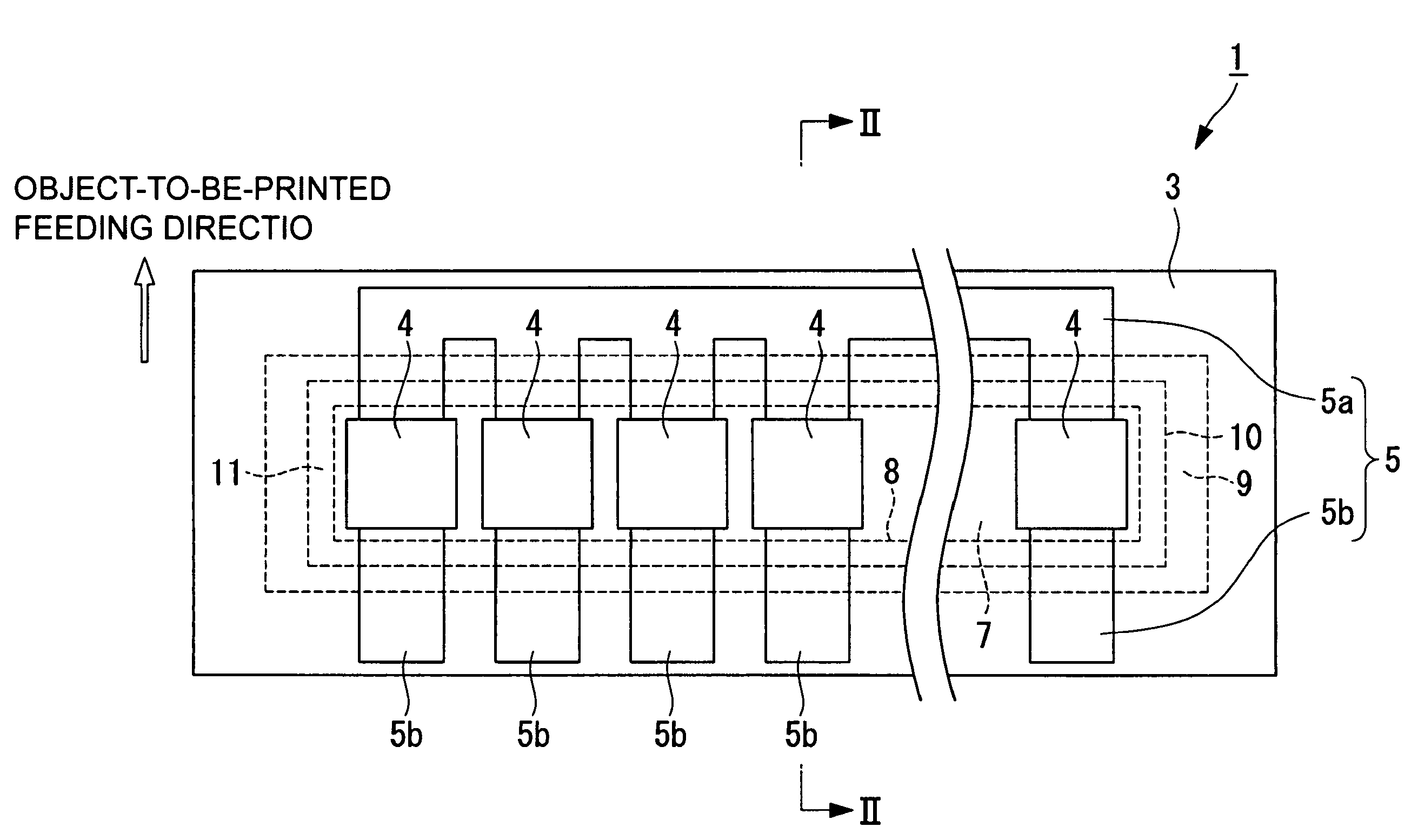
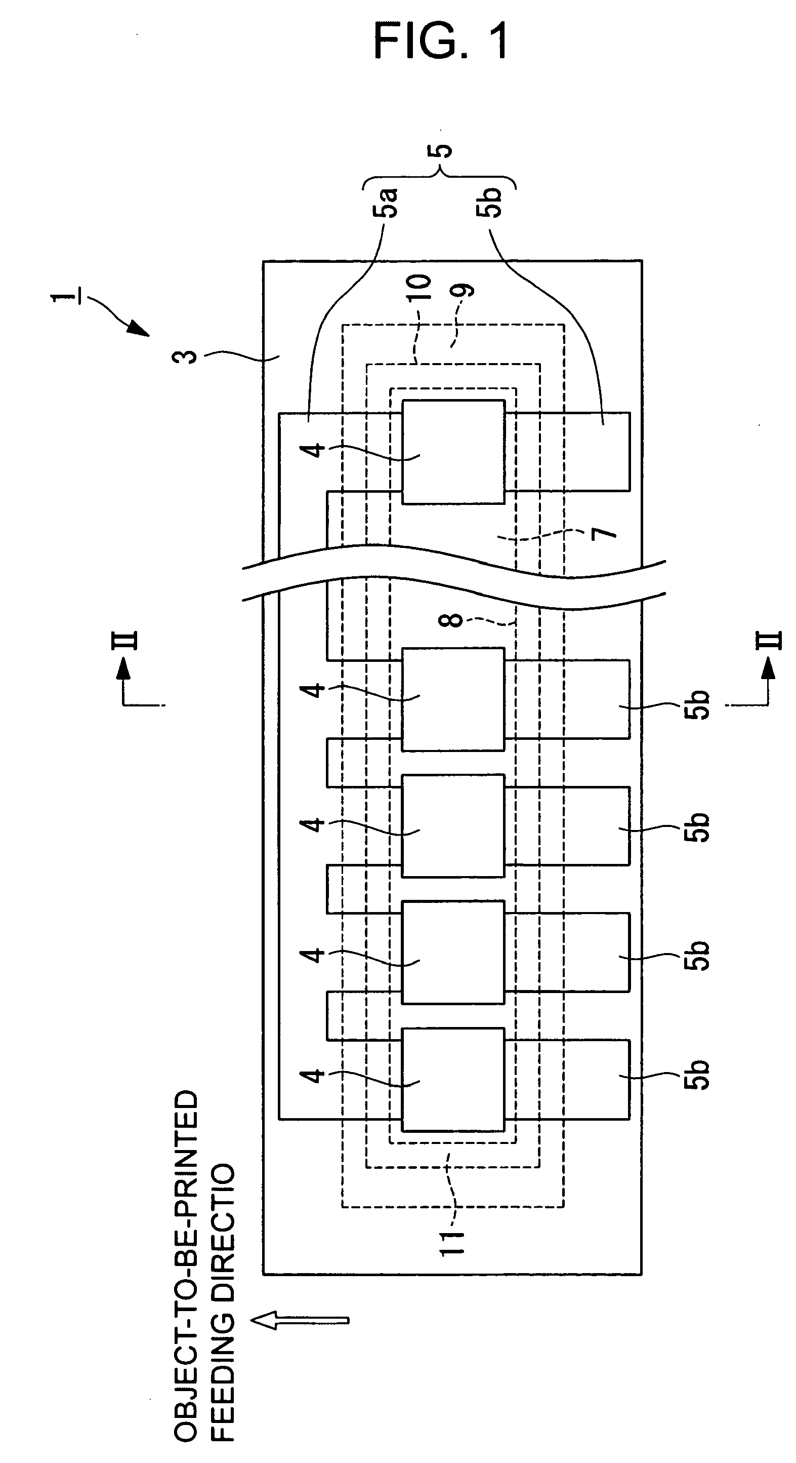
[0038]Hereinafter, a heating resistance element component according to the present invention is described with reference to FIG. 1 to FIG. 5.

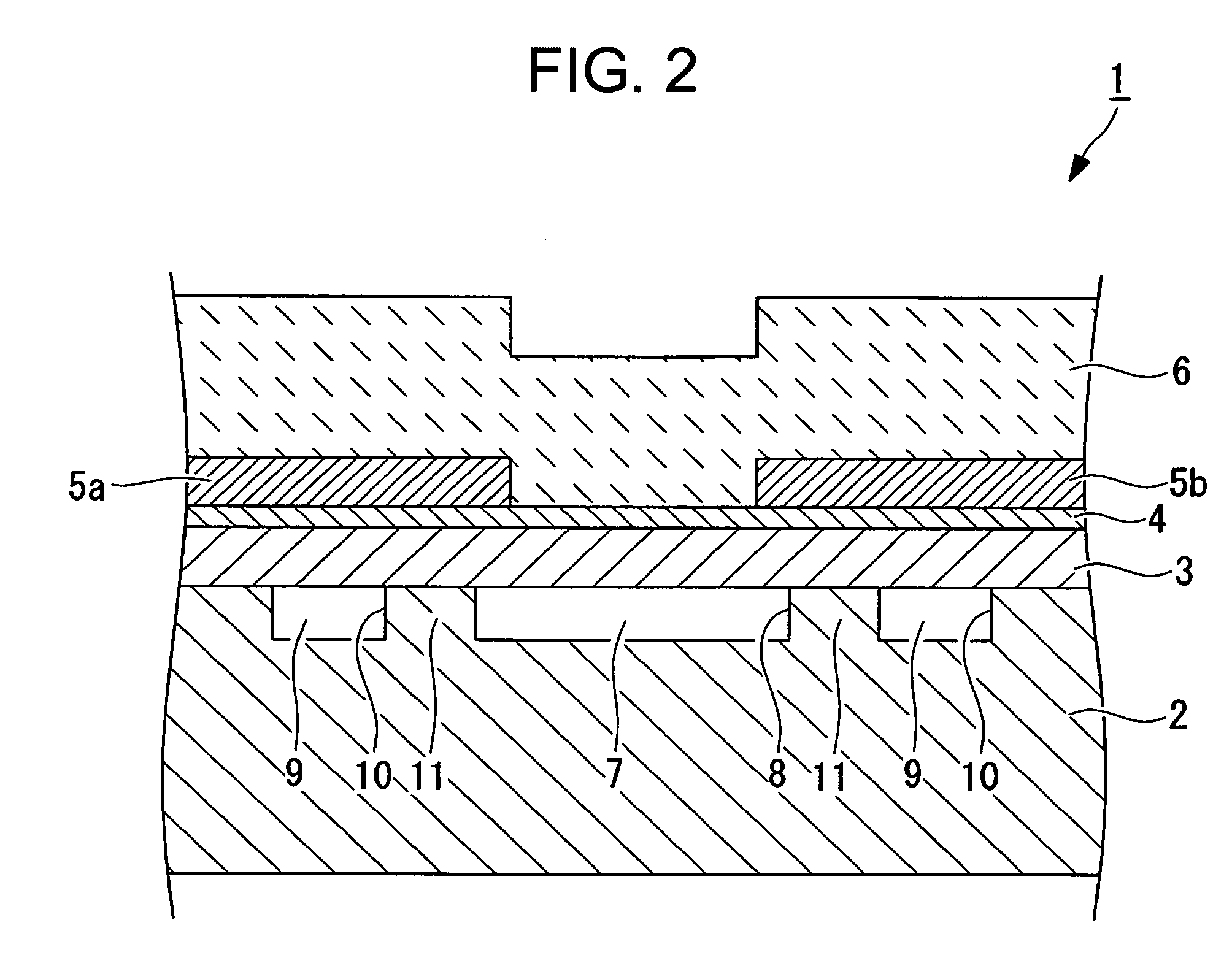
[0039]FIG. 1 is a plan view of a thermal head which is a heating resistance element component according to this embodiment, which shows a state where a protective film is removed. FIG. 2 is a view taken along an arrow II-II of FIG. 1. FIGS. 3A to 3E are flow charts for describing a method of manufacturing the thermal head which is a heating resistance element component according to this embodiment. FIG. 4 is a graph showing calculation results of heating efficiency of the thermal head with a thickness of an undercoat (insulating film) being as a parameter. FIG. 5 is a graph showing calculation results of the heating efficiency of the thermal head with a thickness of a first void heat insulating layer and a thickness of a second void heat insulating layer being as a parameter.

[0040]A heating resistance element component 1 according to this embod...

second embodiment

[0067]A thermal head according to the present invention is described with reference to FIG. 6.

[0068]FIG. 6 is a plan view of the thermal head according to this embodiment, which shows a state where the protective film is removed.

[0069]As shown in FIG. 6, a thermal head 21 according to this embodiment is different from the thermal head 1 described above according to the first embodiment in that a second concave portion 22 is formed in place of the second concave portion 10. Other components of the thermal head 21 are the same as those of the thermal head 1 described above according to the first embodiment, and thus their descriptions are omitted here.

[0070]The second concave portion 22 includes a concave portion 22a which extends linearly along the arrangement direction of the heating resistors 4 on the common wire 5a side and a concave portion 22b which extends linearly along the arrangement direction of the heating resistors 4 on the individual wire 5b side.

[0071]The concave portio...

third embodiment

[0074]A thermal head according to the present invention is described with reference to FIG. 7.

[0075]FIG. 7 is a plan view of the thermal head according to this embodiment, which shows a state where the protective film is removed.

[0076]As shown in FIG. 7, a thermal head 31 according to this embodiment is different from the thermal head 1 described above according to the first embodiment in that first concave portions 32 are formed in place of the first concave portion 8. Other components of the thermal head 31 are the same as those of the thermal head 1 described above according to the first embodiment, and thus their descriptions are omitted here.

[0077]The first concave portions 32 are concave portions which are formed along the arrangement direction of the heating resistors 4 such that first hollow portions (first void heat insulating layers) 33 are individually located in respective regions covered by the heating portions of the heating resistors 4 (such that rear surfaces of the ...


PUM


Abstract

Provided is a heating resistance element component, including: a supporting substrate; an insulating film laminated on the supporting substrate; a plurality of heating resistors arranged at intervals on the insulating film; a common wire connected to one end of each of the plurality of heating resistors; and individual wires each connected to another end of the each of the plurality of heating resistors, in which a surface of the supporting substrate is formed with a first concave portion and a second concave portion, the first concave portion being arranged in a region opposed to heating portions of the plurality of heating resistors, the second concave portion being arranged at an interval in a vicinity of the first concave portion. Accordingly, heating efficiency of the heating resistors can be increased to reduce power consumption, and a strength of the substrate under the heating resistors can be increased.

Description

BACKGROUND OF THE INVENTION[0001]1. Field of the Invention[0002]The present invention relates to a heating resistance element component (thermal head) which is used in a thermal printer typically mounted onto a compact information equipment terminal such as a compact handy terminal, and is used for performing printing on a thermal recording medium through selective driving of a plurality of heating elements based on print data.[0003]2. Description of the Related Art[0004]Recently, thermal printers are widely used in compact information equipment terminals. The compact information equipment terminals are driven by a battery, which leads to strong demands for electric power saving of the thermal printers. Accordingly, there have been growing demands for thermal heads having high heating efficiency.[0005]As to increasing efficiency of the thermal head, there is a method of forming a heat insulating layer as a lower layer of a heating resistor (for example, see JP 2004-34601 A). Among a...

Claims


Application Information

Patent Timeline
Patent Type & Authority Applications(United States)
IPC IPC(8): H05B1/00H05B3/02B41J2/335
CPCB41J2/33585B41J2/3357
Inventor MOROOKA, TOSHIMITSUSANBONGI, NORIMITSUSATO, YOSHINORISHOJI, NORIYOSHIKOROISHI, KEITARO
Owner SEIKO INSTR INC
Why Eureka
Try Eureka