Decoding distorted symbols

a technology of distorted symbols and decoding, applied in the field of reading symbols, can solve the problems of inability to meet conditions, difficulty in automatic identification, and inability to achieve the effect of avoiding excessive computational complexity and avoiding compromised burst noise handling

Inactive Publication Date: 2009-04-09
COGNEX TECH & INVESTMENT
View PDF28 Cites 24 Cited by
  • Summary
  • Abstract
  • Description
  • Claims
  • Application Information

AI Technical Summary

Benefits of technology

[0007]The invention enables reading of distorted optical symbols using known locating and decoding methods, without requiring a separate and elaborate camera calibration procedure, without excessive computational complexity, and without compromised burst noise handling. The invention exploits a distortion-tolerant method for locating and decoding 2D code symbols to provide a correspondence between a set of points in an acquired image and a set of points in the symbol. Then, a coordinate transformation is constr

Problems solved by technology

Therefore, the readers are required to not only deal with multiple symbologies, but also variation caused by printing errors and optical distortion.
Difficulties arise when these two conditions cannot be satisfied due either to the geometry of the product, or to a spatial limitation as to where the reader can be placed with respect to the product.
The expected geometric characteristics of the finder pattern of a symbology in question may be distorted to an extent that an automated identification is difficult and time consuming, if not impossible.
However, this solution requires some undesirable trade-offs.
It not only slows down the process of locating and decoding a symbol due to a

Method used


Image

  • Decoding distorted symbols
  • Decoding distorted symbols
  • Decoding distorted symbols

Examples


Embodiment Construction

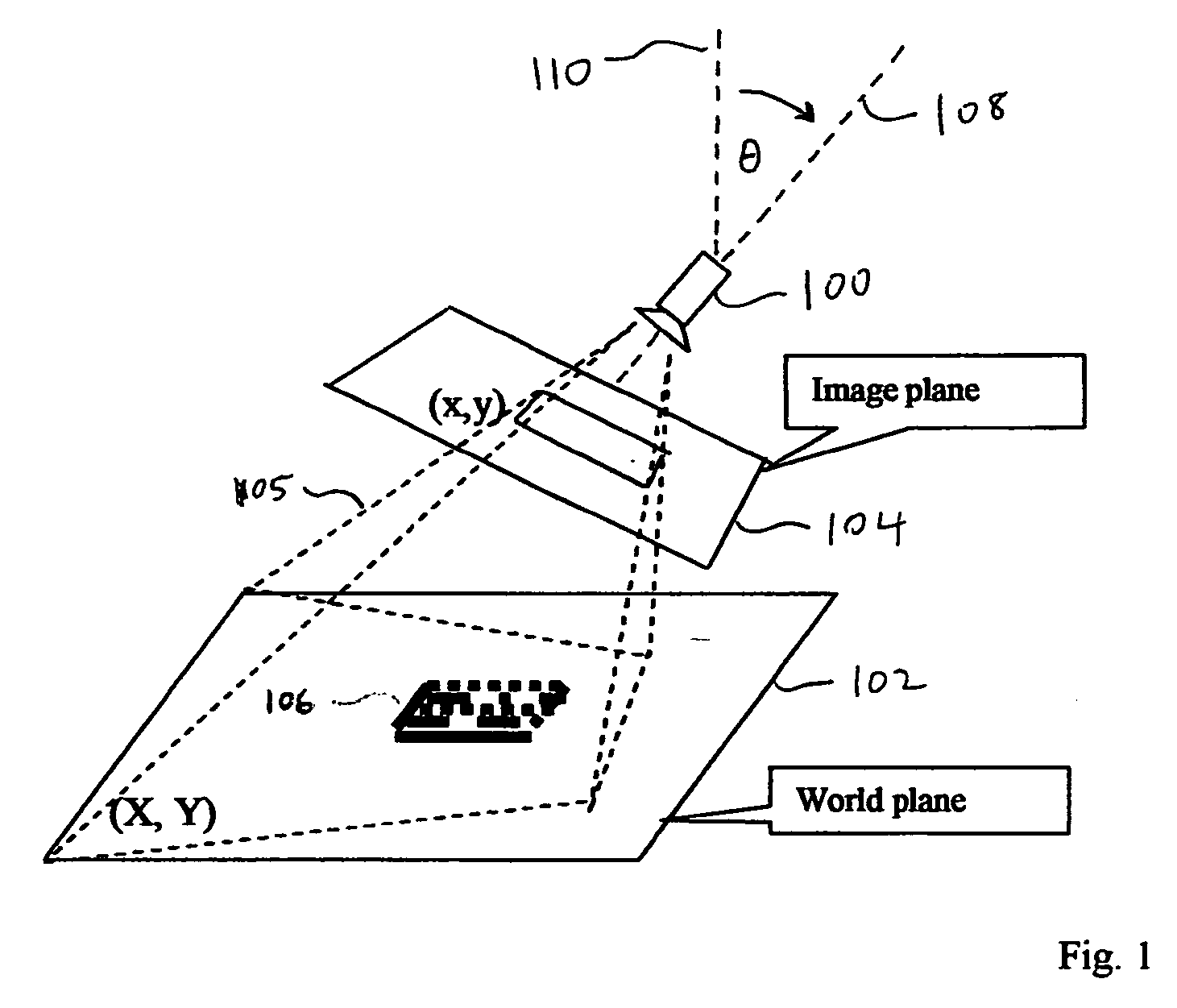
[0050]Referring to FIG. 1, a preferred embodiment of the invention provides methods for calibrating a projective camera model of a camera 100, for which a perspective transformation 105 exists, between a world plane 102 and an image plane 104. The world plane 102 bears a code symbol 106.

[0051]In general, the method of the invention can be used with other camera models, such as a simplified model with variable zoom, or a more complicated model including a lens with barrel or pin-cushion distortion, and with transformations other than geometric transformations and perspective transformations, such as a polynomial transformation, as long as a correspondence can be established using multiple feature points, as will be explained further below.

[0052]The method of the invention is applicable to mounted cameras for reading symbols, as well as to “portable” symbol readers, provided that the incident angle θ between an optical axis 108 of the camera (or the symbol reader) and a normal vector ...


PUM


Abstract

A method is provided for reading distorted optical symbols using known locating and decoding methods, without requiring a separate and elaborate camera calibration procedure, without excessive computational complexity, and without compromised burst noise handling. The invention exploits a distortion-tolerant method for locating and decoding 2D code symbols to provide a correspondence between a set of points in an acquired image and a set of points in the symbol. A coordinate transformation is then constructed using the correspondence, and run-time images are corrected using the coordinate transformation. Each corrected run-time image provides a distortion-free representation of a symbol that can be read by traditional code readers that normally cannot read distorted symbols. The method can handle both optical distortion and printing distortion. The method is applicable to “portable” readers when an incident angle with the surface is maintained, the reader being disposed at any distance from the surface.

Description

FIELD OF THE INVENTION[0001]This invention relates to reading symbols using machine vision, and particularly to enhanced location and / or decoding of distorted symbols.BACKGROUND OF THE INVENTION[0002]Automated identification of products using optical codes has been broadly implemented throughout industrial operations for many years. Optical codes are patterns composed of elements with different light reflectance or emission, assembled in accordance with predefined rules. The elements in the optical codes may be bars or spaces in a linear barcode, or a regular polygonal shape in a two-dimensional matrix code. The bar code or symbols can be printed on labels placed on product packaging, or directly on the product itself by direct part marking. The information encoded in a bar code or symbol can be decoded using various laser scanners or optical readers in fixed-mount installations, or portable installations.[0003]Various business operations have come to rely upon the accuracy and avai...

Claims


Application Information

Patent Timeline
IPC IPC(8): G06K7/10G06K9/40
CPCG06T3/00G06K7/14
Inventor YE, XIANGYUNNADABAR, SATEESHA
Owner COGNEX TECH & INVESTMENT
Why Eureka
Try Eureka