
Head substrate, printhead, head cartridge, and printing apparatus

a printing apparatus and head substrate technology, applied in printing, other printing apparatus, etc., can solve the problems of unstable ink discharge, degrading print quality, increasing current consumption of the whole head substrate, etc., to prevent any unnecessary increase in the temperature of the head substrate, stable ink droplet discharge, and suppress power consumption in the standby state of printing operation

Inactive Publication Date: 2009-04-09
CANON KK
View PDF9 Cites 22 Cited by
  • Summary
  • Abstract
  • Description
  • Claims
  • Application Information

AI Technical Summary

Benefits of technology

[0019]For example, a head substrate employing a constant current drive method according to the present invention is capable of preventing an increase in printhead temperature and stably discharging ink by suppressing power consumption in a standby state without printing.
[0020]With this head substrate, a printhead which prevents an increase in printhead temperature and stably discharges ink, a head cartridge incorporating the printhead, and a printing apparatus using the printhead are implemented.
[0034]The invention is particularly advantageous since current supply is controlled, e.g., control is performed such that current supply except the printing timing, i.e., in the standby state is stopped, power consumption in the printing operation standby state can be suppressed.
[0035]Hence, any unnecessary increase in head substrate temperature can be prevented, contributing to stable ink droplet discharge. Hence, high-quality printing can be achieved.

Problems solved by technology

When the number of reference currents increases, current consumption of the whole head substrate increases.
This increase in temperature makes ink discharge unstable or degrades the print quality.

Method used


Image

  • Head substrate, printhead, head cartridge, and printing apparatus
  • Head substrate, printhead, head cartridge, and printing apparatus
  • Head substrate, printhead, head cartridge, and printing apparatus

Examples


first embodiment

[0087]FIG. 5 is a block diagram showing the arrangement of a heater driving circuit provided on the head substrate of a printhead according to the first embodiment. The same reference numerals as in the prior art denote the same constituent elements in FIG. 5, and a description thereof will be omitted.

[0088]FIG. 5 shows a reference current circuit 107 in addition to a reference voltage circuit 105, voltage-to-current conversion circuit 104, and current source block 106. The current source block 106 comprises n current source blocks 1061 to 106n having the same arrangement. A switch 108 is inserted in the voltage-to-current conversion circuit 104 to ON / OFF-control a reference current (Iref).

[0089]The voltage source for the reference voltage circuit 105 preferably outputs a voltage stable with respect to the power supply voltage or a temperature change. Hence, the reference voltage circuit 105 obtains a voltage stable with respect to the power supply voltage or a temperature change by...

second embodiment

[0111]FIG. 9 is a block diagram showing the arrangement of a heater driving circuit provided on the head substrate of a printhead according to the second embodiment. The same reference numerals as in the prior art and the first embodiment denote the same constituent elements in FIG. 9, and a description thereof will be omitted.

[0112]The switch 108 of the first embodiment controls supply of the reference current (Iref). On the other hand, according to a characteristic arrangement of the second embodiment, n switches 1091 to 109n are inserted in a reference current circuit 107 to control supply of a plurality of reference currents IR1 to IRn generated on the basis of a reference current (Iref) generated by a voltage-to-current conversion circuit 104.

[0113]Hence, according to this embodiment, energization control is executed such that the reference currents IR1 to IRn are supplied to any desired switches by control signals Vs1, Vs2, . . . , Vsn supplied to the switches 1091 to 109n.

[01...

third embodiment

[0145]FIG. 16 is a block diagram showing the arrangement of a heater driving circuit provided on the head substrate of a printhead according to the third embodiment. The same reference numerals as in the prior art and first and second embodiments denote the same constituent elements in FIG. 16, and a description thereof will be omitted.

[0146]According to the first embodiment, the switch 108 to control supply of the reference current (Iref) is provided in the voltage-to-current conversion circuit 104. According to the second embodiment, the n switches 1091 to 109n to control supply of the plurality of reference currents IR1 to IRn generated on the basis of the reference current (Iref) generated by the voltage-to-current conversion circuit 104 are provided in the reference current circuit 107. According to a characteristic arrangement of the third embodiment, switches to control supply of a reference current (Iref) and reference currents IR1 to IRn are provided in both a voltage-to-cu...


PUM


Abstract

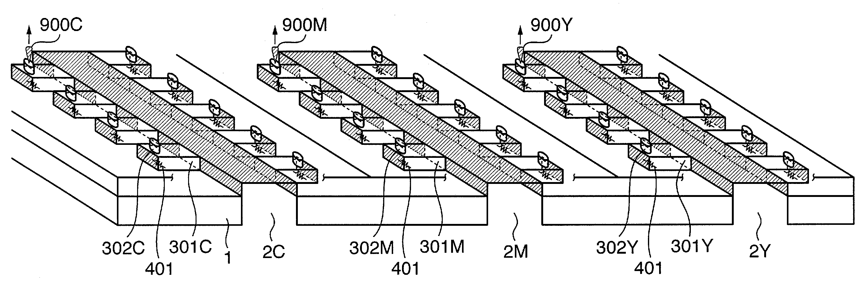
This invention is directed to: a printhead substrate which employs a constant current driving method and can suppress power consumption in a standby state, prevent an increase in printhead temperature, and stably discharge ink; a printhead using the printhead substrate; a head cartridge incorporating the printhead; and a printing apparatus using the printhead. The head substrate includes a plurality of printing elements; a plurality of driving elements which are provided in correspondence with the plurality of printing elements and drive the plurality of printing elements; a reference voltage generation circuit which generates a reference voltage; a reference current generation circuit which generates a first reference current on the basis of the generated reference voltage; a plurality of constant current sources, each of which generates a constant current to drive the plurality of printing elements on the basis of the generated first reference current; and a switch which controls supply of the first reference current in accordance with a printing operation.

Description

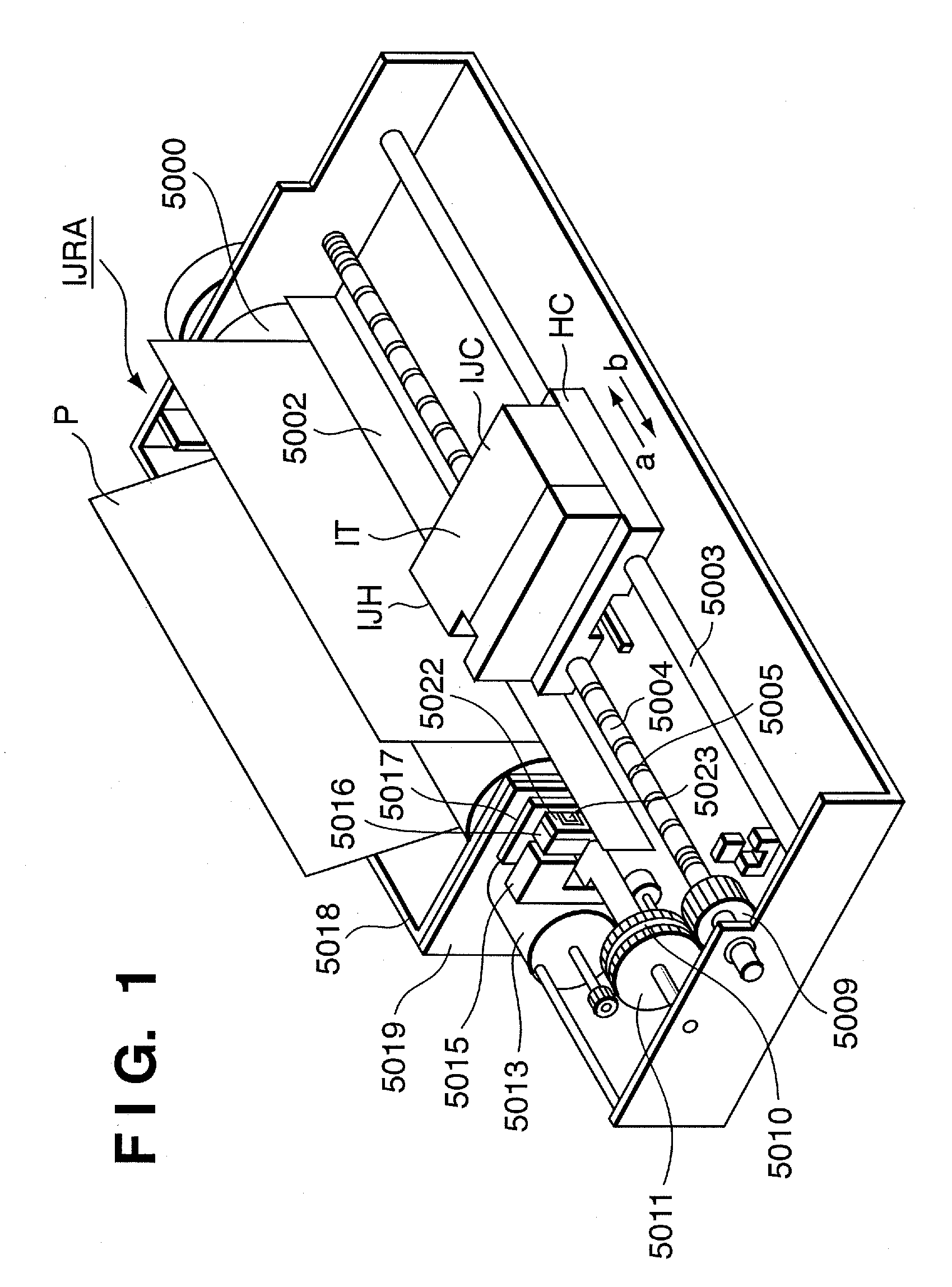
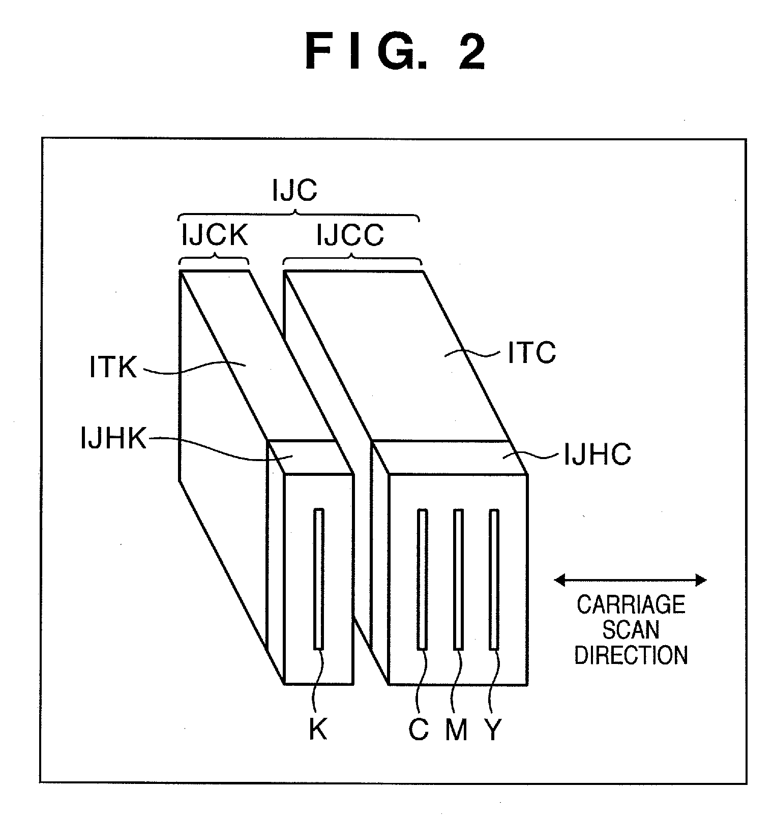
TECHNICAL FIELD[0001]This invention relates to a head substrate, printhead, head cartridge, and printing apparatus. More particularly, this invention relates to a head substrate, printhead, head cartridge, and printing apparatus which are used to, e.g., execute printing according to an inkjet method and have a circuit to drive a printing element by supplying a predetermined current to it.BACKGROUND ART[0002]Conventionally, an inkjet printhead (to be referred to as a printhead hereinafter) is known which causes a heater arranged in each nozzle of the printhead to generate thermal energy, makes ink near the heater bubble by using the thermal energy, and discharges the ink from the nozzles by bubble to execute printing.[0003]Recent inkjet printing apparatuses using the printhead are required to have high printing speed and high resolution. To meet this requirement, many nozzles are implemented in the printhead at a high density. As for driving of the heaters in the printhead, there is ...

Claims


Application Information

Patent Timeline
Patent Type & Authority Applications(United States)
IPC IPC(8): B41J29/38
CPCB41J2/04541B41J2/0458B41J2/04555B41J2/0457B41J2/17546B41J29/38
Inventor HIRAYAMA, NOBUYUKISAKURAI, MASATAKA
Owner CANON KK
Learn More