
Image Forming Device, and Method and Computer Readable Medium Therefor

a technology of image forming and forming device, which is applied in the direction of electrographic process apparatus, visual presentation, instruments, etc., can solve the problems of image quality deterioration and image quality might not be sufficiently secured, and achieve the effect of ensuring image quality

Active Publication Date: 2009-04-09
BROTHER KOGYO KK
View PDF2 Cites 12 Cited by
  • Summary
  • Abstract
  • Description
  • Claims
  • Application Information

AI Technical Summary

Benefits of technology

[0009]Aspects of the present invention are advantageous to provide one or more improved image forming devices, methods, and computer readable media that make it possible to secure image quality provided by the image forming devices.
[0011]In some aspects of the present invention, one of the first regions on the rotational body in which the intended image is to be formed by the forming unit is specified based upon the variation of the positional deviations of the images within each of the first regions. Thereby, for instance, a first region that shows therein a small degree of variance of the positional deviations of the images can be specified as a region in which the intended image is to be formed by the forming unit in preference to any other first region that shows therein a larger variance of positional deviations of images. Thus, it is possible to secure quality of an image formed. It is noted that a first region beginning with a phase may partially overlap another first region beginning with a different phase on the rotational body.
[0013]In the method configured as above, one of the first regions on the rotational body in which the image is to be formed is specified based upon the variation of the positional deviations of the patterns within each of the first regions. Thereby, for instance, a first region that shows a small degree of variance of the positional deviations of the patterns therein can be specified as a region in which the image is to be formed in preference to any other first region that shows a larger variance of the positional deviations of the patterns therein. Thus, it is possible to secure the quality of the image.

Problems solved by technology

Therefore, when the average value throughout the entire circumference of the sheet carrying belt is utilized in the case where a sheet is conveyed in the region, the image quality is deteriorated.
Thus the image quality might not sufficiently be secured.

Method used


Image

  • Image Forming Device, and Method and Computer Readable Medium Therefor
  • Image Forming Device, and Method and Computer Readable Medium Therefor
  • Image Forming Device, and Method and Computer Readable Medium Therefor

Examples


Embodiment Construction

[0026]It is noted that various connections are set forth between elements in the following description. It is noted that these connections in general and, unless specified otherwise, may be direct or indirect and that this specification is not intended to be limiting in this respect. Aspects of the invention may be implemented in computer software as programs storable on computer-readable media including but not limited to RAMs, ROMs, flash memory, EEPROMs, CD-media, DVD-media, temporary storage, hard disk drives, floppy drives, permanent storage, and the like.

[0027]Hereinafter, an embodiment according to aspects of the present invention will be described with reference to the accompany drawings.

[0028](Overall Configuration of Printer)

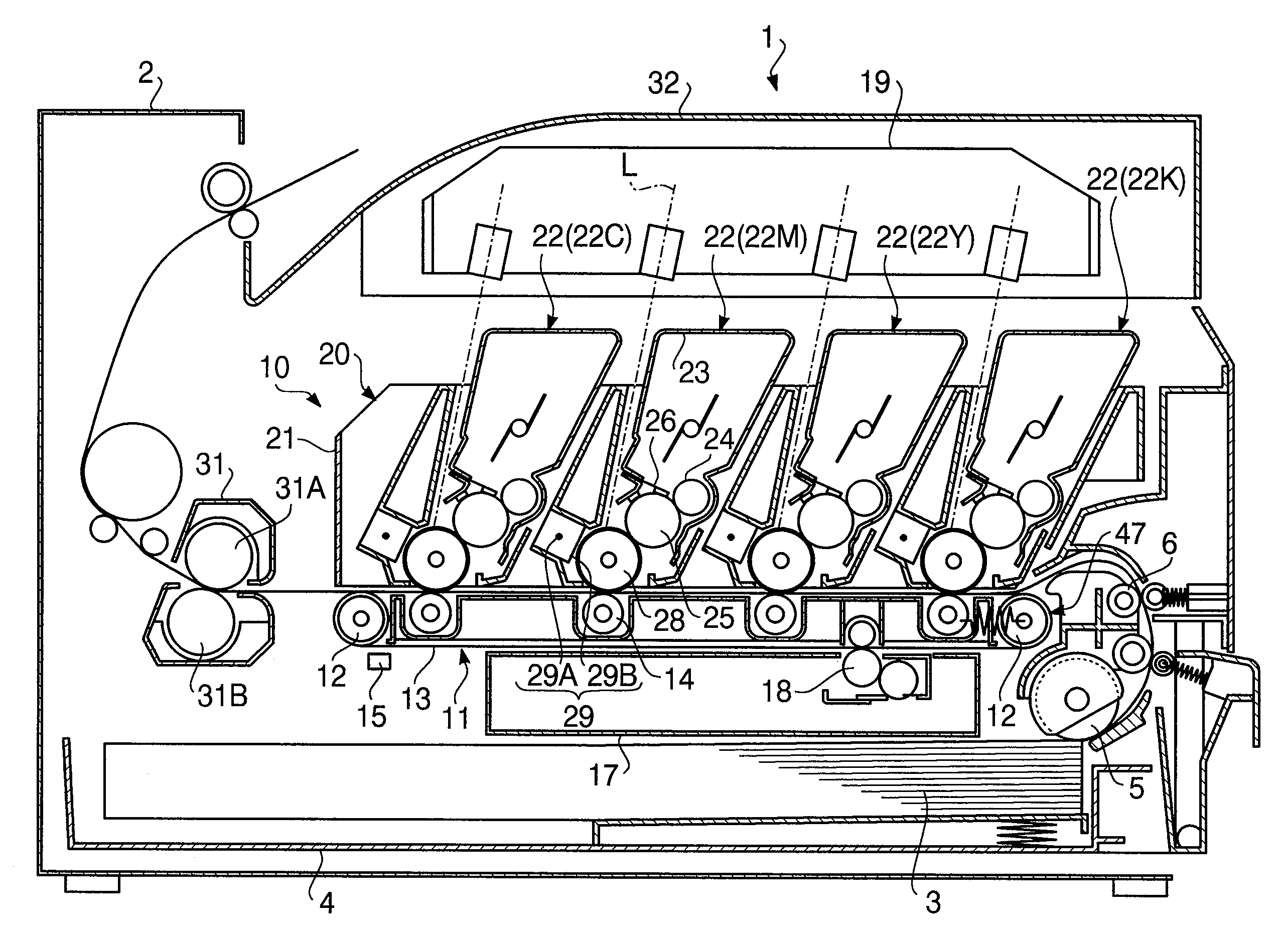
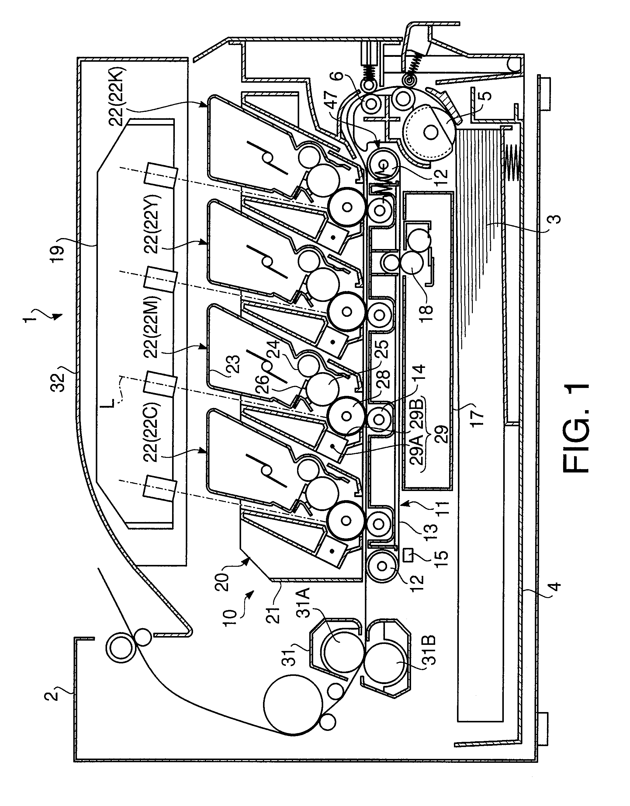
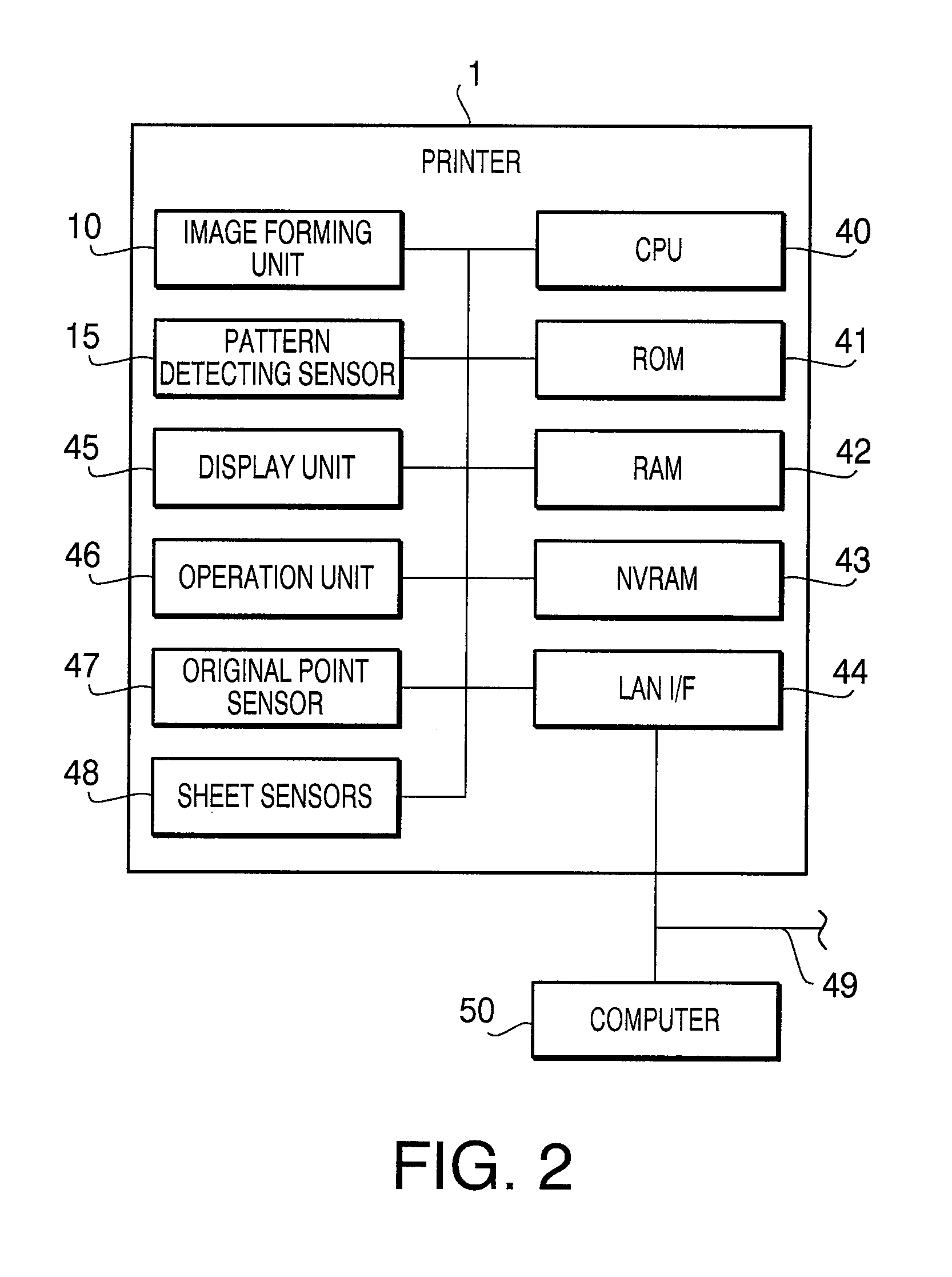
[0029]FIG. 1 is a cross-sectional side view schematically showing a configuration of a printer 1 according to aspects of the present invention. It is noted that the following description will be given under an assumption that a right side of FIG. 1 is ...


PUM


Abstract

An image forming device includes a rotational body carrying a sheet thereon, the rotational body including first regions defined thereon that begin with respective different phases on the rotational body, a forming unit forming an image on one of the rotational body and the sheet carried on the rotational body, a storage unit storing thereon information regarding positional deviations of images formed within each of the first regions, a region specifying unit that determines a variation of the positional deviations of the images within each of the first regions based upon the information stored and specifies one of the first regions based upon the determined variation, and a control unit controlling the forming unit to form an intended image of which an image forming position is corrected based upon the information stored, in the first region specified on the rotational body.

Description

CROSS-REFERENCE TO RELATED APPLICATION[0001]This application claims priority under 35 U.S.C. §119 from Japanese Patent Application No. 2007-262356 filed on Oct. 5, 2007. The entire subject matter of the application is incorporated herein by reference.BACKGROUND[0002]1. Technical Field[0003]The following description relates to one or more techniques to correct an image forming property of an image forming device.[0004]2. Related Art[0005]An image forming device such as a color laser printer has been known, which includes a plurality of image forming units aligned along a sheet carrying belt such that toner images of respective different colors are sequentially transferred onto a sheet being conveyed on the sheet carrying belt by the image forming units. In such an image forming device, when the respective toner images are transferred into different positions on the sheet by the image forming units, a formed image becomes a low-quality one.[0006]In order to secure the quality of the i...

Claims


Application Information

Patent Timeline
IPC IPC(8): G06K15/00
CPCG03G15/167G03G15/50G06K15/129G03G2215/0161G06K15/1219G03G15/5062
Inventor KUSHIDA, TSUYOSHI
Owner BROTHER KOGYO KK
Learn More