Image forming system utilizing network camera

Inactive Publication Date: 2009-04-09
CANON KK
View PDF4 Cites 21 Cited by
  • Summary
  • Abstract
  • Description
  • Claims
  • Application Information

AI Technical Summary

Benefits of technology

[0013]The present invention is directed to a method for efficiently performing pull p

Problems solved by technology

However, the user authentication by using biometric information can save only the user's trouble of inputting the user ID and the password, but the problem that the user needs to wait in front of the image forming apparatus for a long tim

Method used


Image

  • Image forming system utilizing network camera
  • Image forming system utilizing network camera
  • Image forming system utilizing network camera

Examples


Example

First Exemplary Embodiment

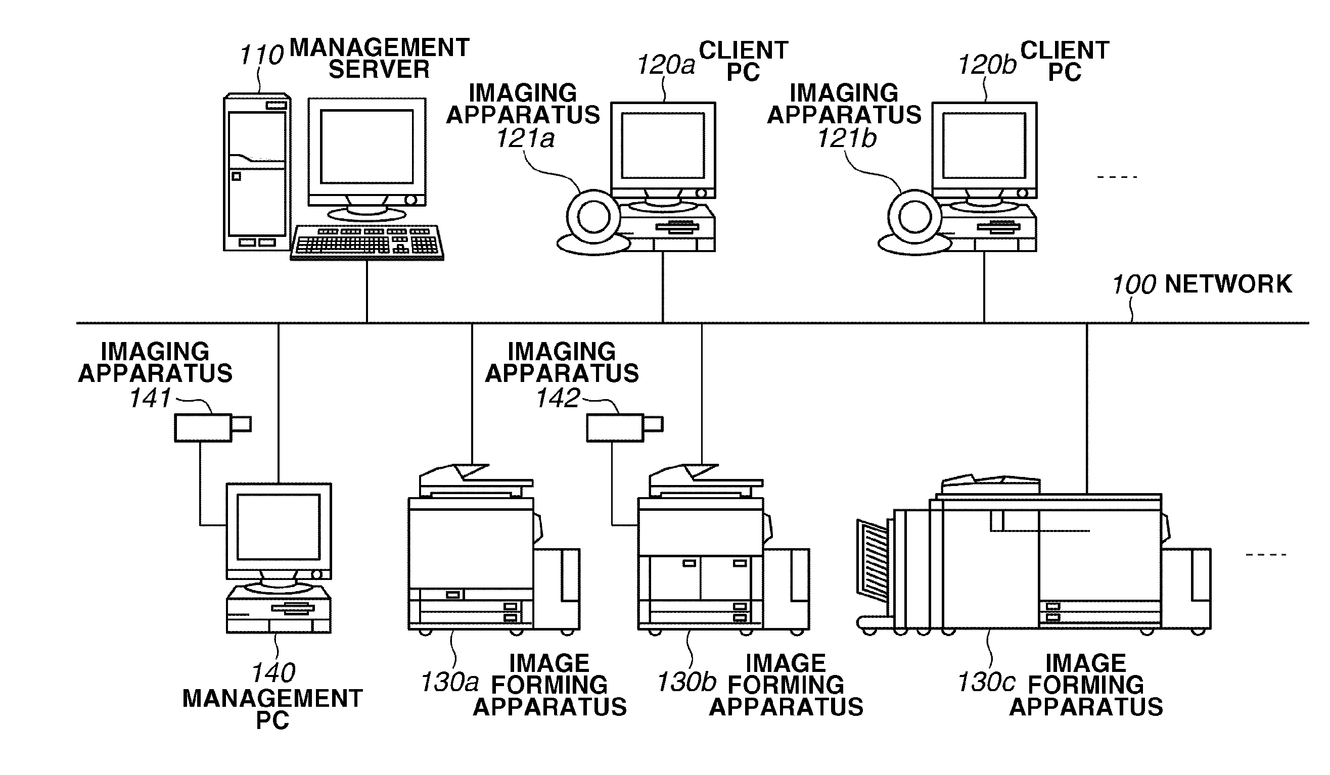
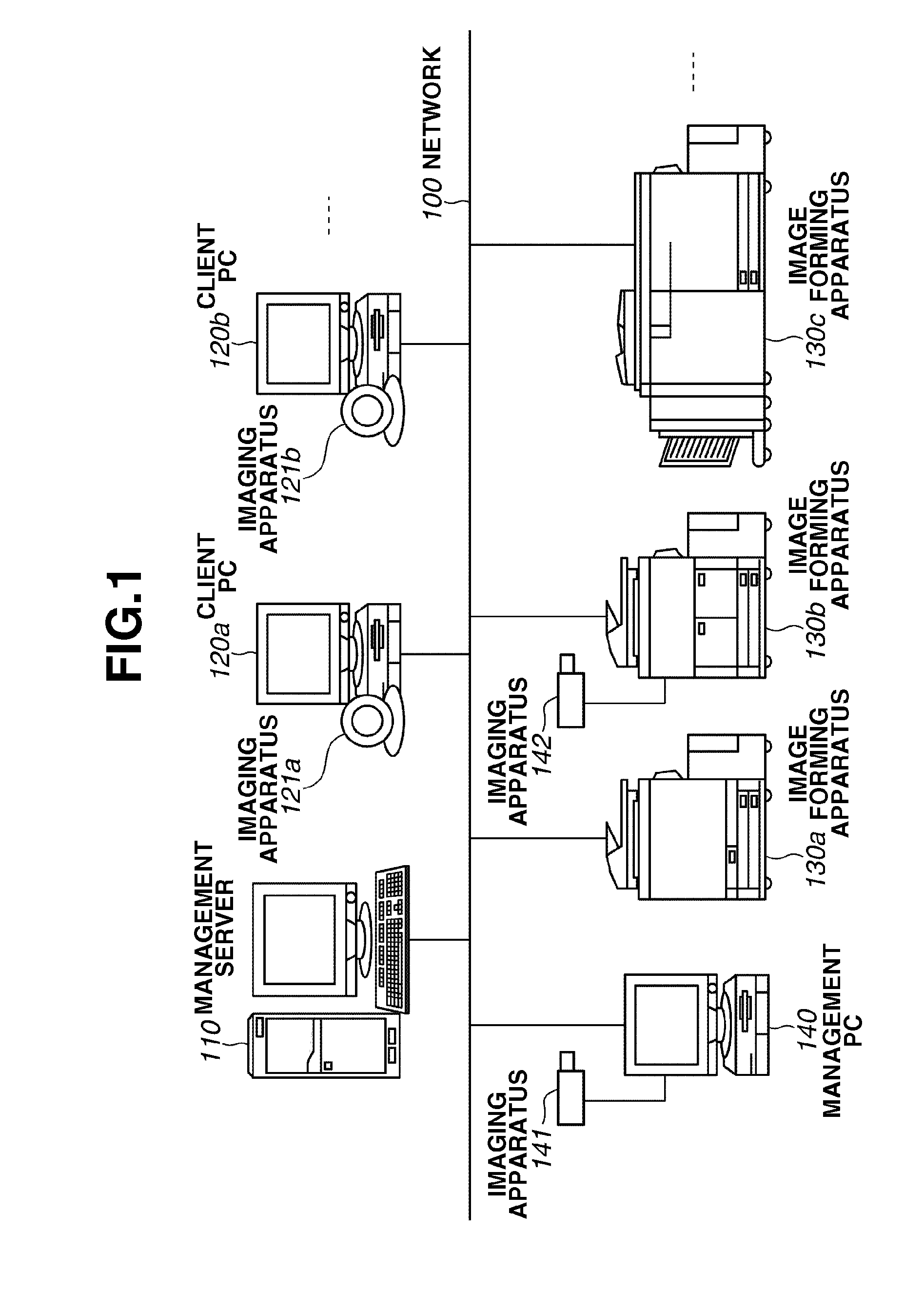
[0045]A first exemplary embodiment of the present invention is described below. FIG. 1 illustrates an example of an entire configuration of an image forming system according to the first exemplary embodiment of the present invention. In the example illustrated in FIG. 1, the image forming system includes a plurality of image forming apparatuses, a plurality of client PCs, and a management server which are communicably connected with one another via a network 100.

[0046]Referring to FIG. 1, a management server 110, client PCs 120a and 120b, and image forming apparatuses 130a through 130c for printing are connected via the network 100. The management server 110 manages document data input and registered by a user and face image data of the user. The face image data is used as authentication information for searching for and acquiring the document data registered in the management server 110.

[0047]An imaging apparatus 121a is connected to the client PC 120a and...

Example

Second Exemplary Embodiment

[0185]A second exemplary embodiment is different from the first exemplary embodiment in only a point that the user is required to enter the password in registering and printing the document data. Accordingly, only the difference point is described in the following.

[0186]FIG. 12 is a flowchart illustrating an example of data processing performed by the information processing apparatus according to the present exemplary embodiment. The example illustrated in FIG. 12 describes the processing for causing the user to enter the password (the user identification information) and sending the data after encryption thereof, which is performed when the user operates the client PC 120a to issue the request for printing document data.

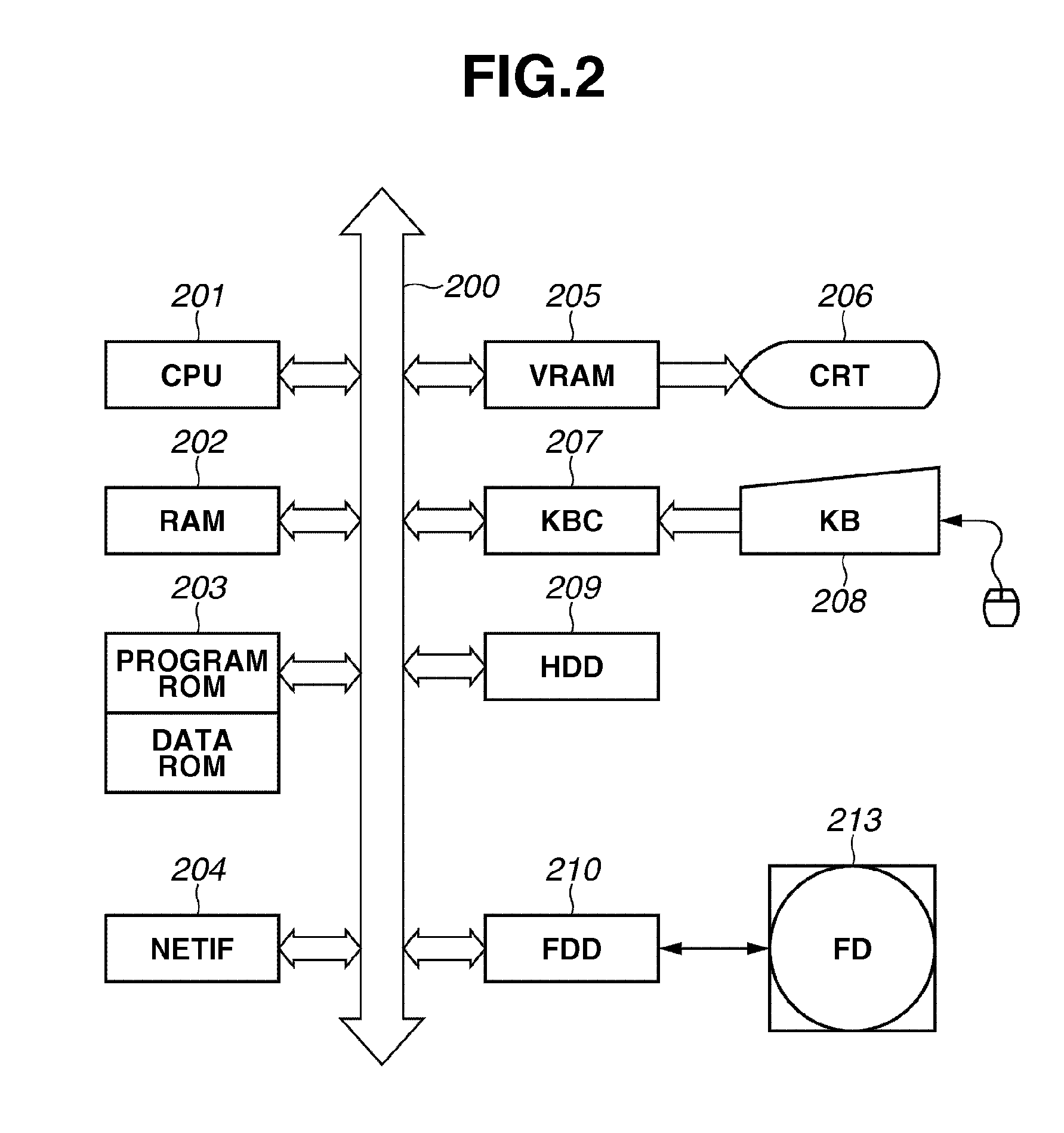
[0187]Each step is implemented by the CPU of the client PC 120a that loads the control program (including the processing module) stored in the HDD 209, the FD 213, or the ROM 203 on the RAM 202 and executes the control program.

[0188]In the...

Example

Third Exemplary Embodiment

[0233]A third exemplary embodiment is different from the first and the second exemplary embodiments in a point that the timing for entering the password is set before displaying the list on the pull printing screen. Accordingly, only the point different from the first and the second exemplary embodiments is described.

[0234]FIG. 17 is a flowchart illustrating an example of data processing performed by the image forming apparatus according to the present exemplary embodiment. The example illustrated in FIG. 17 is a case where the user operates the touch panel unit 1001 of the image forming apparatus 130b to select the pull printing tab 1023.

[0235]Each step is implemented by the CPU of the image forming apparatus 130b that loads the control program (including the processing module) stored in the HDD 209, the FD 213, or the ROM 203 on the RAM 202 and executes the control program.

[0236]The example illustrated in FIG. 17 is different from the processing illustrat...


PUM


Abstract

When a client PC receives a request for printing output data, an imaging apparatus captures an image of a user. The image data of the user captured by the imaging apparatus and the output data is transferred to a management server. The management server performs predetermined image processing on the acquired image data, calculates a characteristic amount of the image data of the user, and registers the calculated characteristic amount and the output data by associating with each other. When the user requests printing of the output data from an image forming apparatus, image data of the user captured by the imaging apparatus is transferred to the management server. The management server calculates a characteristic amount of the acquired image data of the user, compares the calculated characteristic amount with the characteristic amount in the management server, and transfers the output data to the image forming apparatus.

Description

BACKGROUND OF THE INVENTION[0001]1. Field of the Invention[0002]The present invention relates to data processing performed by an image forming system including a plurality of image forming apparatuses, management apparatuses, and information processing apparatuses.[0003]2. Description of the Related Art[0004]In recent years, along with demand for security of a print product and a print method as well as an increased number of image forming apparatuses, a print environment in an office or public facilities has been changed. As one of such changes, demand for a “pull printing system” has increased. The “pull printing system” refers to a system in which an image forming apparatus acquires document data from a server and prints the acquired document data.[0005]In the pull printing system, a user generally inputs a user identification (ID) and a password via an input unit of the image forming apparatus and searches for document data registered in the server.[0006]Then, the image forming ...

Claims


Application Information

Patent Timeline
IPC IPC(8): G06K1/00
CPCG06F3/1296G06F21/32G06F21/608H04N1/4433H04N1/00233H04N1/4406H04N1/4426H04N1/00222G06F3/1222G06F3/1238G06F3/1267G06F3/1288
Inventor YOSHIDA, TORU
Owner CANON KK
Why Eureka
Try Eureka