Electric Device with Rotatable and Receivable Plug

a technology of electric devices and receivable plugs, which is applied in the direction of coupling devices, flexible/turnable line connectors, coupling devices, etc., can solve the problems of affecting the use of the plug, the mechanical structure of the foldable or rotatable fixture is usually weak, and the damage of the foldable or rotatable unit is not easy to repair, etc., to achieve the effect of sustaining long-term carrying and frequent use, saving effort and reducing the siz

Active Publication Date: 2009-04-09
PHIHONG TECH CO LTD
View PDF8 Cites 7 Cited by
  • Summary
  • Abstract
  • Description
  • Claims
  • Application Information

AI Technical Summary

Benefits of technology

[0007]One advantage of the present invention is the rotatable plug which is receivable conveniently into the electric device.
[0008]Another advantage of the present invention is the rotatable plug which is effort-saving in use.
[0009]Still another advantage of the present invention is the rotatable plug which can meet the safety requirements.
[0010]Still another advantage of the present invention is the rotatable plug which is durable and robust by utilizing the fixing member coupled to the lower case and can sustain long-term carrying and frequent usage.
[0011]Another advantage of the present invention is that the rotatable plug can be applied to any kinds of electric devices which need an electric plug.
[0012]These and other advantages will become apparent from the following description of preferred embodiments taken together with the accompanying drawings and the appended claims.

Problems solved by technology

Many conventional foldable, rotatable or retractable plugs similar to the above plug have a major difficulty in the mechanical design.
The conventional foldable or rotatable fixtures usually have weak mechanical structure for attaching to either the housing or other members of the plug connector.
The weak attachment structure may cause the foldable or rotatable unit to be damageable, less reliable and even dangerous to the user and may also affect the establishment or maintenance of a good electric contact.

Method used


Image

  • Electric Device with Rotatable and Receivable Plug
  • Electric Device with Rotatable and Receivable Plug
  • Electric Device with Rotatable and Receivable Plug

Examples


Embodiment Construction

[0024]The invention will now be described with the preferred embodiments and aspects and these descriptions interpret structure and procedures of the invention only for illustrating but not for limiting the Claims of the invention. Therefore, except the preferred embodiments in the specification, the present invention may also be widely used in other embodiments.

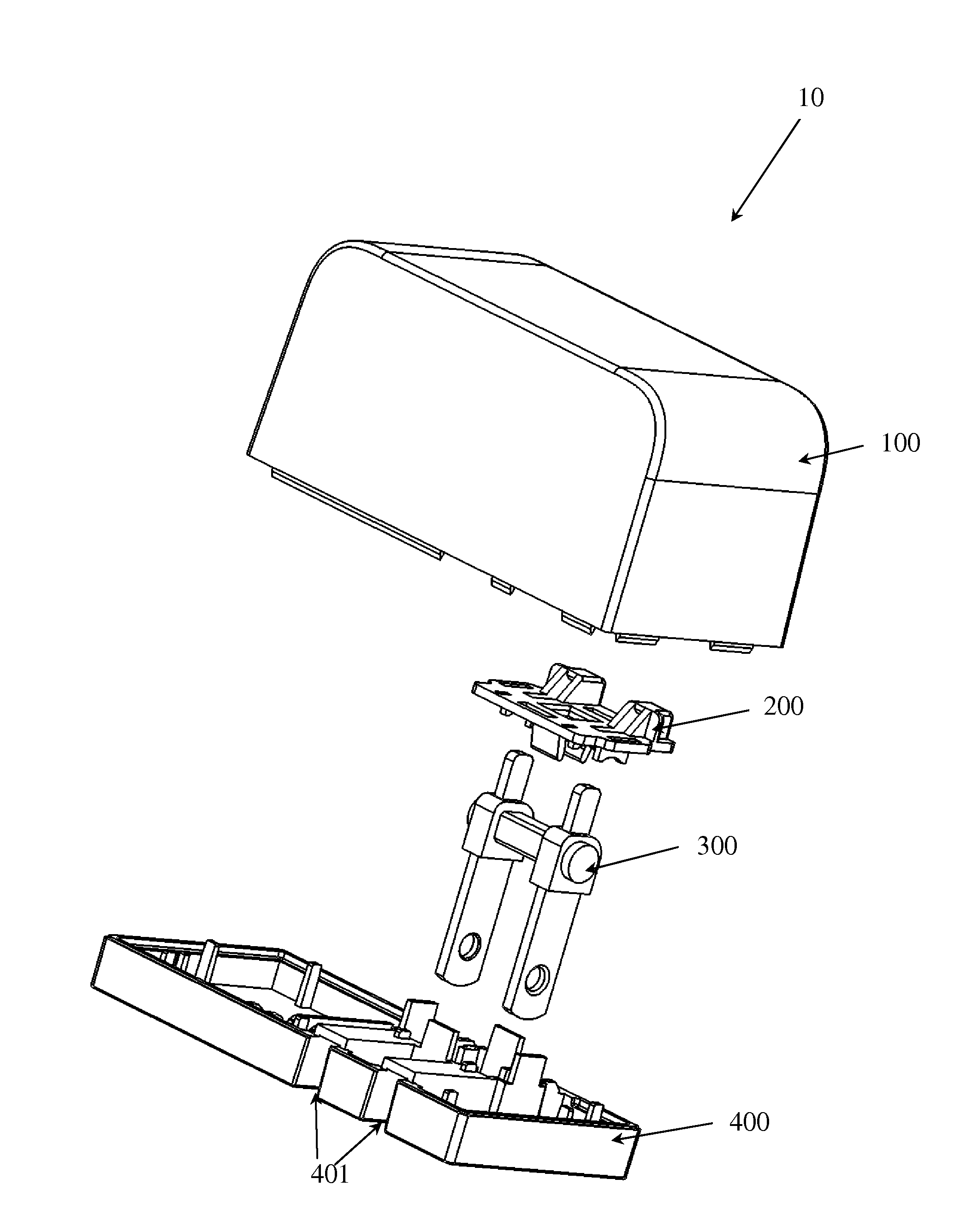
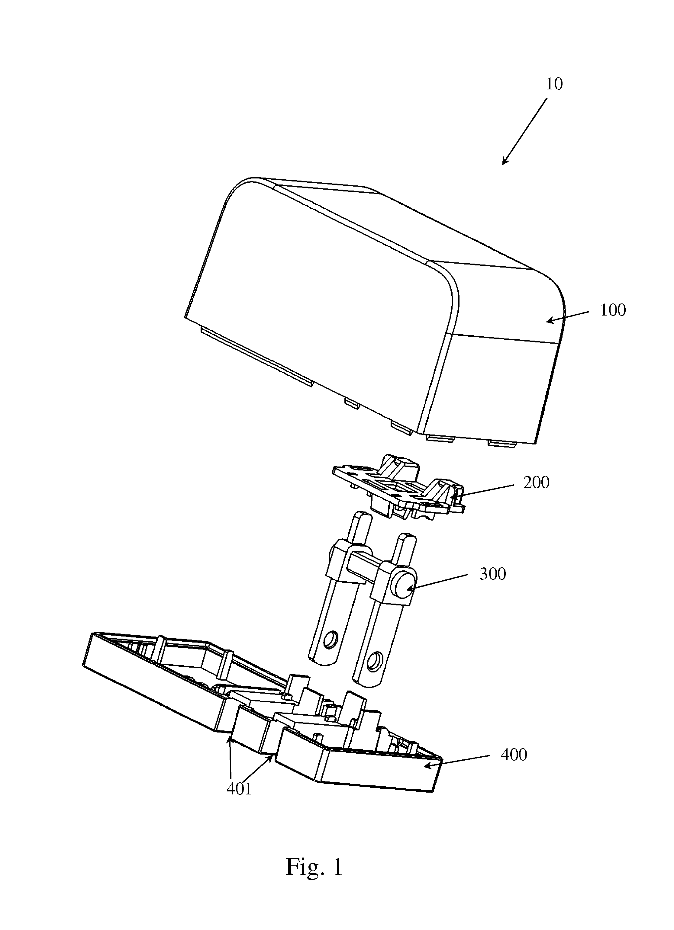
[0025]The present invention discloses an electric device with a rotatable plug. In the preferred embodiment of the present invention, the electric device 10 includes an upper case 100, a lower case 400 mating with the upper case 100, a rotatable rack 300 supported by the lower case 400, a fixing member 200 placed on the rotatable rack 300, and a printed circuit board (PCB) 500 attached on the lower case 400 to electrically connect with the rotatable rack 300 as shown in FIG. 1 and FIG. 10. There are two slots 401 defined in the lower surface of the lower case 400 as shown in FIG. 1 and FIG. 5. The slots 401 are set in parall...


PUM


Abstract

The present invention discloses an electric device with a rotatable and receivable plug. The electric device includes an upper case and a lower case. The lower case has two through holes, two plug receiving slots and two receptacles formed therein, and is engaged with the upper case. The electric device further includes a plug having a first end and a second end. The first end is inserted into the through holes of the lower case. Moreover, the first end of the plug is received in the plug receiving slots of the lower case and the second end of the plug is received in the receptacles of the lower case when the plug is rotated to a hidden position. The electric device further includes a fixing member having two slots formed therein to be inserted by the second end of the plug and two clamping fixtures formed on the lower surface thereof to clamp the plug, and a circuit board attached onto the lower case.

Description

FIELD OF THE INVENTION[0001]The present invention relates to an electric device with a plug, and more particularly to an electric device with an effort-saving, receivable, and rotatable plug.BACKGROUND OF THE INVENTION[0002]Consumer electronic products, such as notebooks, personal digital assistants (PDA), mobile phones, MP3 players, and so on, are trending toward smaller sizes continuously, which thereby promotes higher demand for easily-portable electric power connectors, for example, a power supply, a battery charger, or a transformer. Therefore, the electric power connectors of consumer electronic products need to be made with smaller sizes and less weight, and more convenient for shipment. Furthermore, they must be durable in order to sustain long-term carrying and frequent usage. Each of the consumer electronic products needs a plug on the electric power connectors or on the product itself to supply power thereto, and thus the plug is a necessary unit. Various kinds of plugs c...

Claims


Application Information

Patent Timeline
Patent Type & Authority Applications(United States)
IPC IPC(8): H01R13/66
CPCH01R13/502H01R13/60H01R2103/00H01R24/68H01R35/04H01R13/6658
Inventor TSAI, SUNG-NIEN
Owner PHIHONG TECH CO LTD
Why Eureka
Try Eureka