Apparatus for providing high resolution images in a mri-device

a technology of high resolution images and mri devices, which is applied in the direction of color television, magnetic variable regulation, television systems, etc., can solve the problems of preventing the normal operation of certain devices, destroying the images generated by mri devices, and limited utility of visual activation methods

Active Publication Date: 2009-04-09
NORDICNEUROLAB
View PDF16 Cites 27 Cited by
  • Summary
  • Abstract
  • Description
  • Claims
  • Application Information

AI Technical Summary

Benefits of technology

[0018]According to the present invention, the above mentioned improvements are solved by means of an apparatus according to the characterizing clauses of claims 1 and 6. Further preferred embodiments and improvements are obtained by the features given in the dependent claims.

Problems solved by technology

A problem with introducing conventional video signals into an MRI device is that very small magnetic fields generated by another device can destroy the images generated by the MRI device.
Conversely, the strong fields generated by the MRI device may prevent the normal operation of certain devices, such as a cathode ray tube (CRT) or liquid display panel (LCD), within the vicinity of the MRI device.
Another problem is that the MRI device is based on the use of radio frequencies that may disrupt signal modulation.
The utility of this method of visual activation is limited by the position of the patient within the scanner tunnel.
Further, the level of ambient light in the MRI magnet room will affect the quality of the image that the patient sees on the screen.
A high level of ambient light will cause the screen image to be washed out.
Therefore, the patient may find it difficult to focus on the video images and may therefore find it difficult to completely relax.
With this type of system, the patient may be distracted by items which are adjacent to the display screen or by people working behind the patient.
Thus, the possibility of being distracted by the external surroundings in addition to the interior of the tunnel further limits the usefulness of this technique for the reduction of anxiety and claustrophobia in patients.
The problem with the fibre optic taper is that it is stationary and the patient must be positioned in a fixed location so as to be able to see the end of the optic taper.
Thus, the disclosure does not address different size patients, patient positioning, or near and far sighted patients.
In addition; the use of a fixed taper will interfere with auxiliary coils, such as head and c-spine coils, that require close proximate to the body.
Current construction of head and c-spine coils is such that the visual field as needed for viewing a fixed positioned fibre taper is either obscured or completely blocked if the fibre taper is utilized.
In particular, the length of the fibre optic bundle employed to carry the video images from the LCD screen to the eyepiece for viewing by the patient is of concern.
As with all transmission systems, a portion of the transmitted parameter is lost during transmission and the longer the transmission path, the greater the loss.
This loss affects the resolution and brightness of the transmitted video image.
Therefore, the resolution and brightness of the transmitted video image is limited by the length of the fibre optic bundle.
Additionally, the longer the fibre optic bundle, the more cumbersome it is to carry the bundle and associated fibre optic equipment into and out of the MRI scanner tunnel.
This situation results in dead pixels, e.g., black spots that appear on the video display.
Further, as the fibre optic bundle is bent and manipulated over a period of time, the number of broken fibres increases.
An increasing number of broken fibres results in a greater number of black spots appearing on the video display.
Eventually, the transmitted image becomes inadequate and distorted.
Thus, long fibre optic bundles are not cost effective.
The limited distance between the patient's head and the head coil would be inadequate to accommodate the goggles employed by known MRI fibre optic systems that (a) position the image from the LCD display within the scanner tunnel or (b) employ a reflecting mirror over the patient's eyes.
Further, this method of visual activation does not include the ability to generate three-dimensional (3D) images for patient viewing since the image is projected onto a single screen.
The inability to create a condition is which the eye and brain perceive a 3D effect prevents virtual reality from being achieved.
Further, the development of new and smaller head coils limits the distance between the patient's head and the head coil, putting restraints on the size of the goggles to be used within the head coil.

Method used


Image

  • Apparatus for providing high resolution images in a mri-device
  • Apparatus for providing high resolution images in a mri-device
  • Apparatus for providing high resolution images in a mri-device

Examples


Embodiment Construction

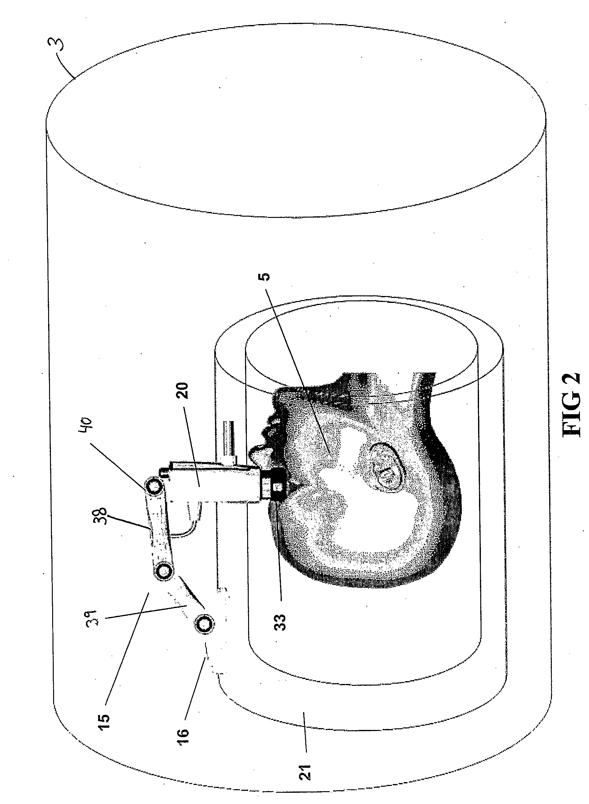
[0024]The following detailed description outlines an MRI compatible visual system having a head coil mounted micro display. In the following description, numerous details such as specific materials and configurations are set forth in order to provide a more complete understanding of the present invention. But it is understood by those skilled in the art that the present invention can be practiced without these specific details. In other instances, well known elements are not described in detail so as not to obscure the present invention. In any event, the scope of the invention is best determined by reference to the appended claims.

General Arrangement

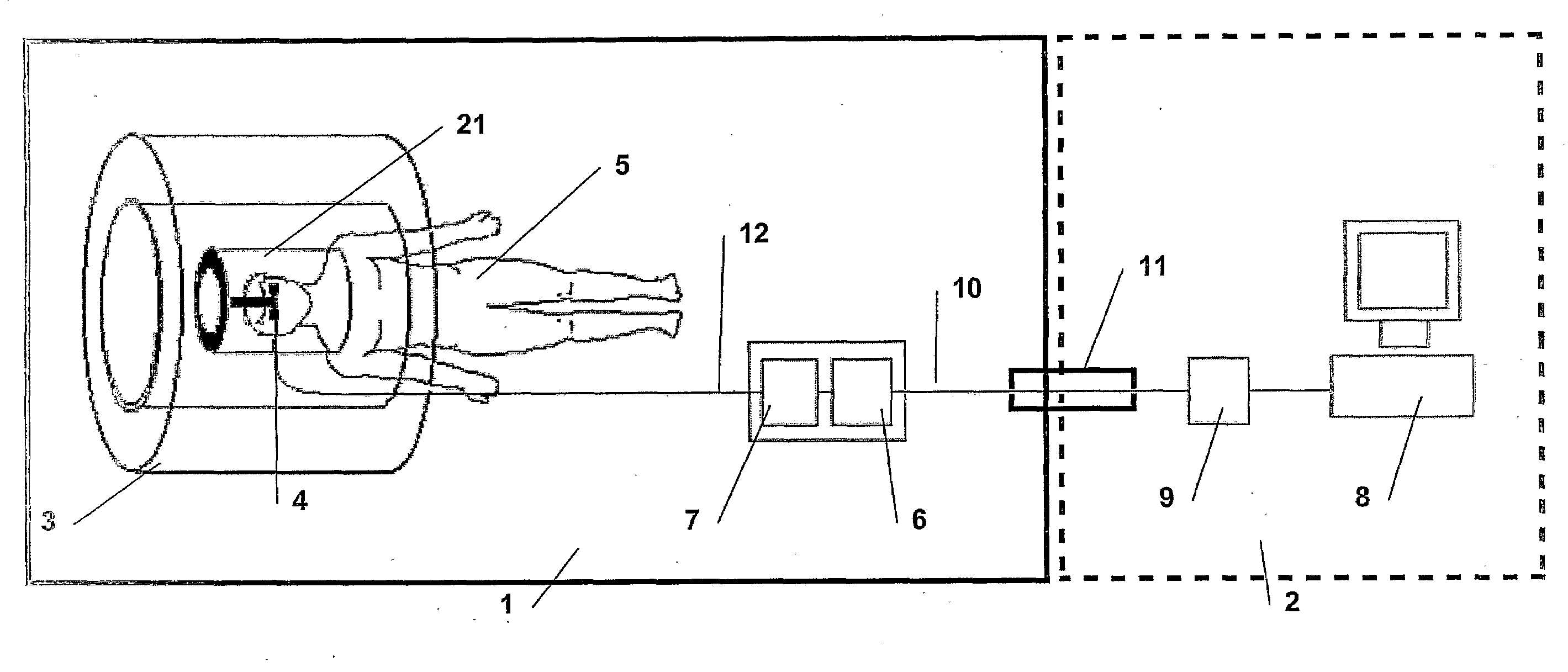
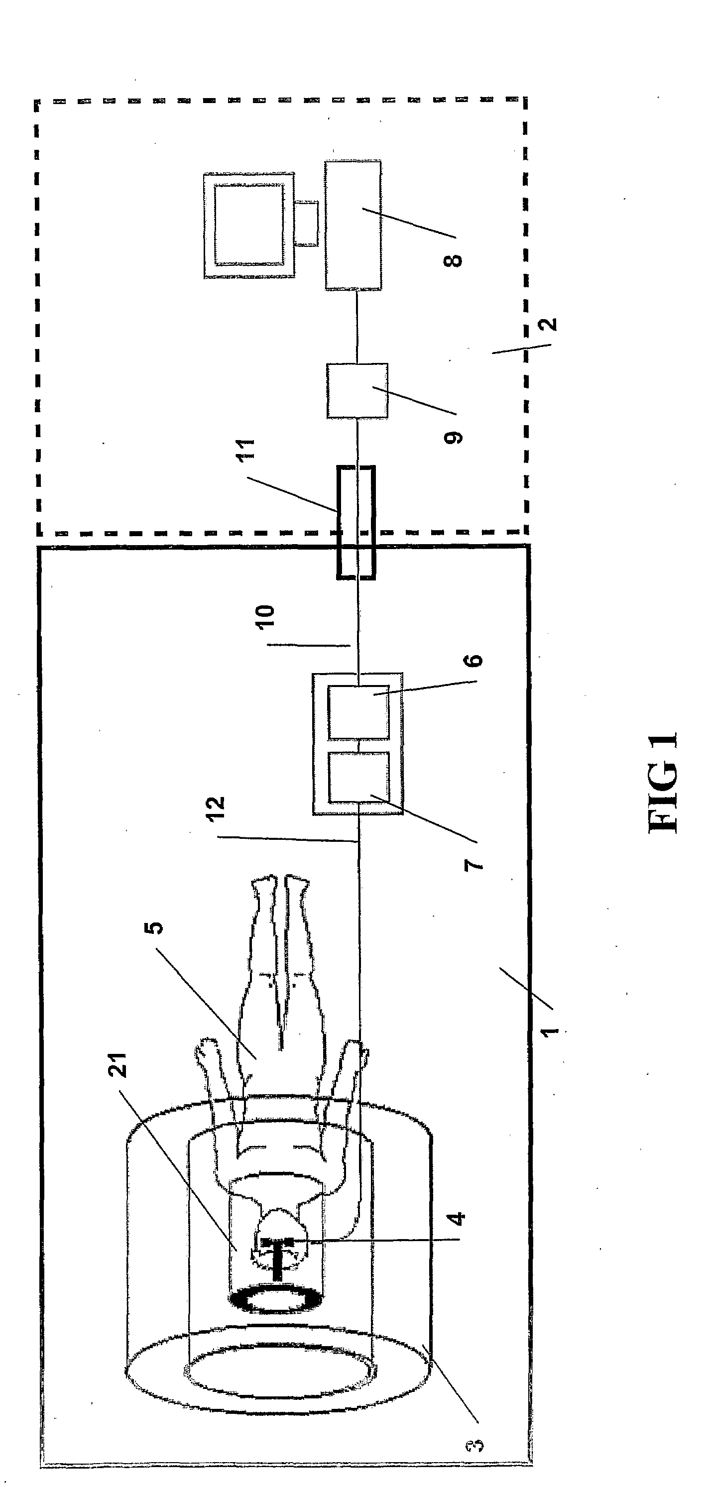
[0025]In a preferred embodiment, the present invention provides an MRI compatible visual system. FIG. 1 gives a general overview of how the present invention system is set up in relation to the MRI system, which is disposed partly in a magnet room 1 and partly in a control room 2.

[0026]One portion of the present invention system is loca...


PUM


Abstract

The present invention relates to an apparatus for providing high resolution images to patients positioned in a magnetic resonance imaging (MRI) device (3), the MRI device (3) comprising a head coil (21), the head coil arranged to surround a patient's (5) head and to provide MRI images thereof, the apparatus comprising means (12, 13, 14) for receiving video or picture image signals from an external source. According to the present invention, the apparatus further comprises means (14, 28, 34, 29) for displaying a video or picture image, said display means being arranged in a housing (20), said housing (20) being suspended in an arm comprising at least two successive members (38, 39), wherein a joint (40) between the housing (20) and the adjacent member (38), a joint or joints (41) between the successive members (38, 39), and a joint (42) between an attachment element (16) for attaching the apparatus to the head coil (21), or other part of the MRI device (3), and the member (39) adjacent to the coil attachment element (16), each is hinged to allow rotation of the joints (40, 41, 42).

Description

FIELD OF THE INVENTION[0001]The present invention relates generally to those products that are used to provide visual stimuli for testing and comforting patients undergoing diagnostic treatment. More specifically, the present invention relates to an apparatus for providing high resolution images to patients positioned in a magnetic resonance imaging (MRI) device.BACKGROUND OF INVENTION[0002]In the medical field, magnetic resonance imaging (MRI) is a commonly used non-invasive technique to diagnose the medical condition of a patient. MRI has the ability to distinguish healthy and diseased tissue, fat and muscle, and between adjacent structures within the body which other imaging modalities cannot demonstrate. MRI utilizes safe radio waves and a magnetic field to generate the images processed by a computer. Typically, the patient is placed within a large homogeneous magnetic field and is subjected to a set of gradient fields and radio frequency (RF) fields. The various fields are accu...

Claims


Application Information

Patent Timeline
Patent Type & Authority Applications(United States)
IPC IPC(8): A61B5/05A61BA61B5/055G01R33/28
CPCG01R33/283A61B5/055
Inventor VANGDAL, VEGARD
Owner NORDICNEUROLAB
Why Eureka
Try Eureka