Multi-function peripheral, power supply apparatus, and power supply control method

Active Publication Date: 2009-04-09
KK TOSHIBA +1
View PDF11 Cites 14 Cited by
  • Summary
  • Abstract
  • Description
  • Claims
  • Application Information

AI Technical Summary

Benefits of technology

[0008]It is an object of the present invention to provide a multi-function peripheral, a power supply apparatus,

Problems solved by technology

Operations of components on a secondary side, which are loads on a power supply circuit, for example, various boards and sensors are also limited in the same manner as this fixing heater.
However, it is difficult to obtain satisfactory power efficiency when o

Method used


Image

  • Multi-function peripheral, power supply apparatus, and power supply control method
  • Multi-function peripheral, power supply apparatus, and power supply control method
  • Multi-function peripheral, power supply apparatus, and power supply control method

Examples


first embodiment

[0026]A digital multi-function peripheral according to the present invention will be hereinafter explained with reference to the accompanying drawings.

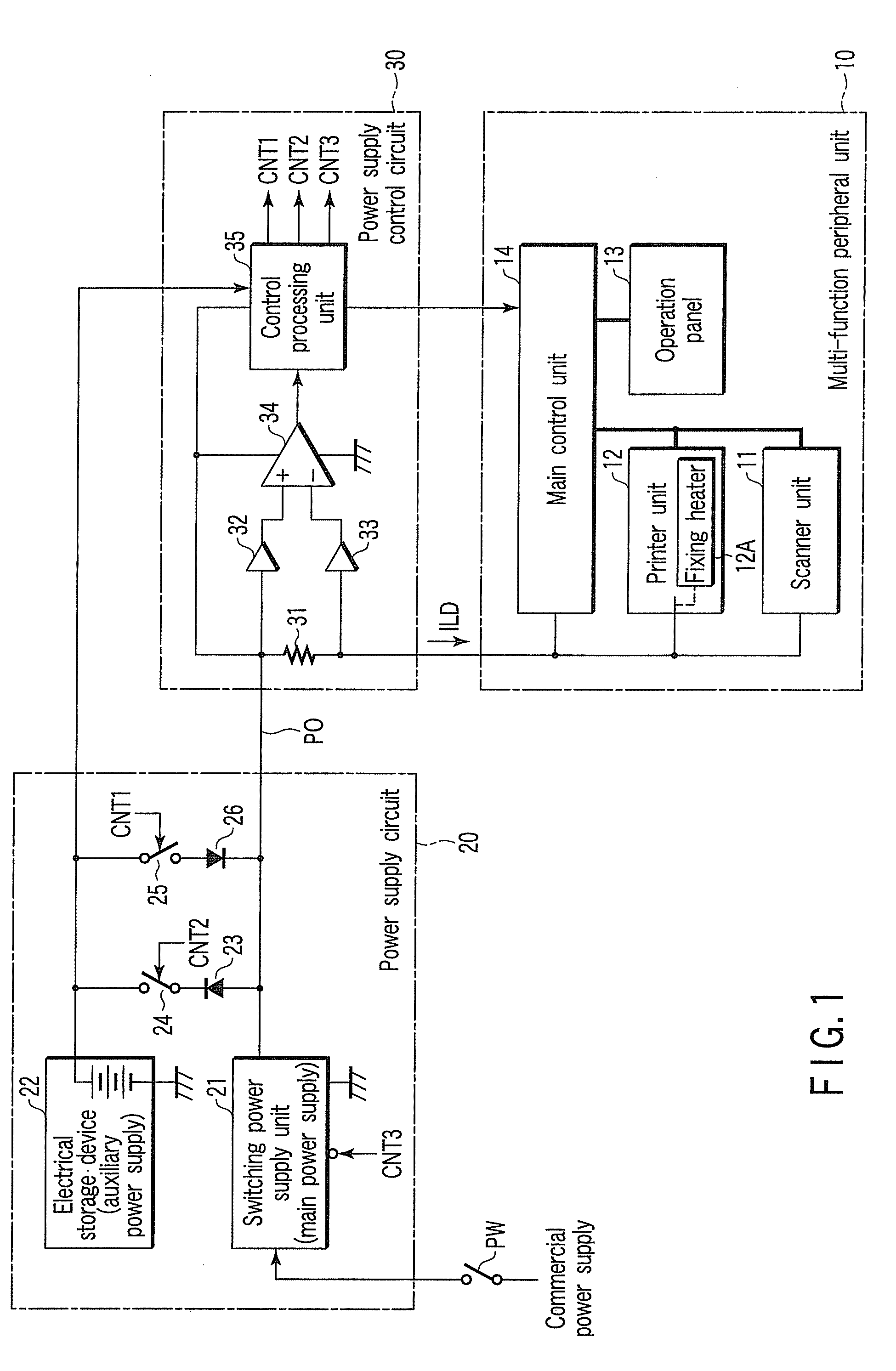
[0027]FIG. 1 schematically shows a circuit configuration of this digital multi-function peripheral. This digital multi-function peripheral includes a multi-function peripheral unit 10 that has a scanner function, a printer function, a copy function obtained by combining the scanner function and the printer function, and the like, a power supply circuit 20 that supplies electric power to this multi-function peripheral unit 10, and a power control circuit 30 that controls the power supply circuit 20 with control signals CNT1 to CNT3.

[0028]The multi-function peripheral unit 10 includes a scanner unit 11 that scans, for example, an image of an original, a printer unit 12 that prints the image on a sheet, an operation panel 13 for performing various kinds of key input and display, and a main control unit 14 that controls the scanner unit 1...

second embodiment

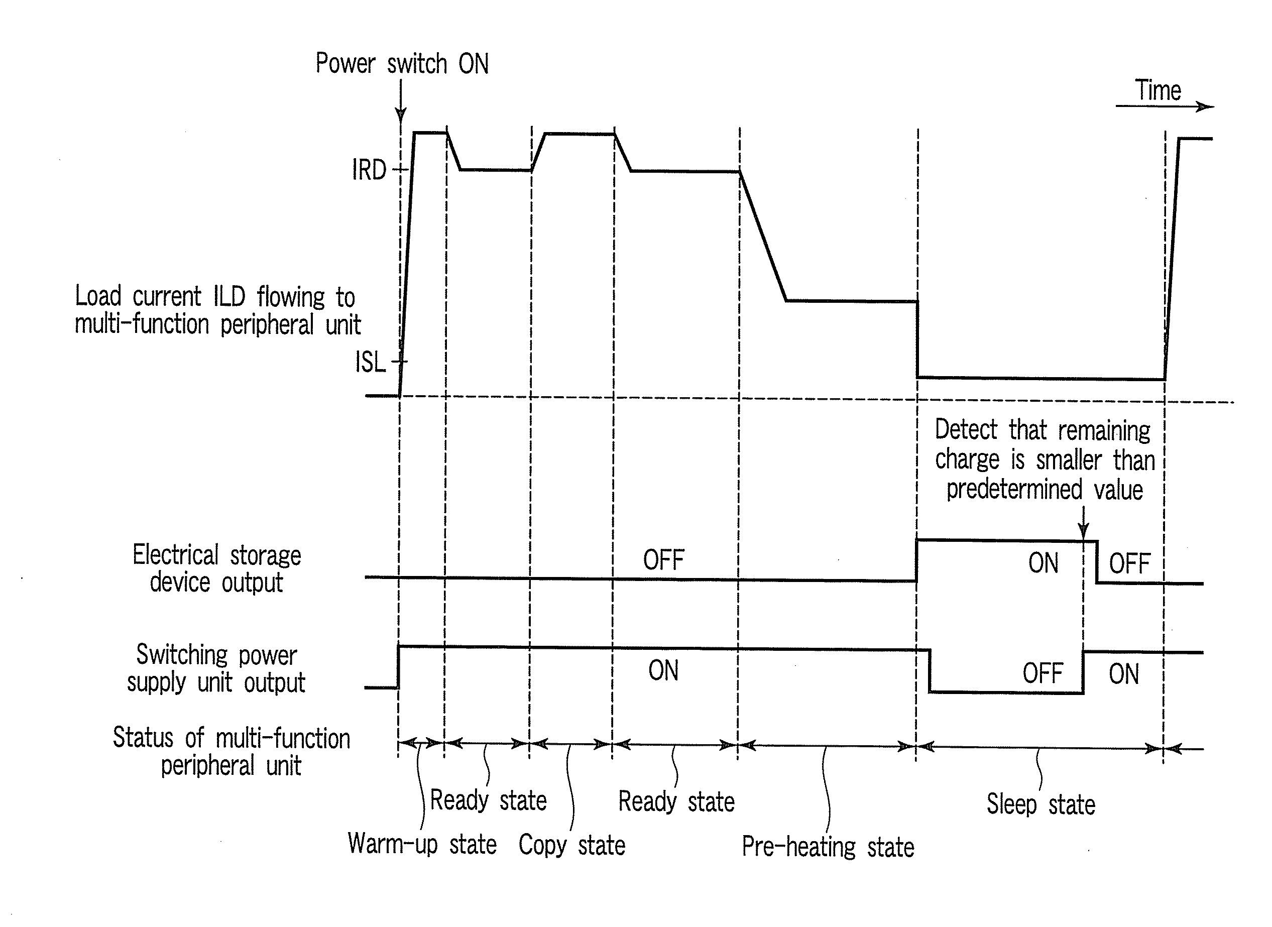
[0048]In the second embodiment, the electrical storage device 22 effectively functions as an auxiliary power supply that feeds an electric current to the fixing heater 12B in warming up the fixing device. It is possible to reduce a warm-up time required for raising the temperature of the fixing device to a predetermined fixing temperature through cooperation of the fixing heaters 12A and 12B and improve convenience. Here, it is important that the electrical storage device 22, which supplies electric power to the multi-function peripheral unit 10 instead of the switching power supply unit 21 in the sleep state, can be used together with the switching power supply unit 21 in the warm-up state in order to supply electric power to the multi-function peripheral unit 10 and the load current ILD is used to confirm the warm-up state.

[0049]Here, an actual change in power consumption in the digital multi-function peripheral according to this embodiment is explained.

[0050]When the multi-functi...


PUM


Abstract

A digital multi-function peripheral includes a multi-function peripheral unit that has plural functions, a switching power supply unit connected to a commercial power supply as a main power supply for the multi-function peripheral unit, and an electrical storage device charged in advance as an auxiliary power supply for the multi-function peripheral unit. The digital multi-function peripheral further includes a control circuit that monitors a load current flowing to the multi-function peripheral unit, supplies electric power from the electrical storage device to the multi-function peripheral unit instead of electric power from the switching power supply unit when the load current is smaller than a threshold set as an allowable lower limit of power efficiency of the switching power supply unit, and supplies the electric power from the switching power supply unit to the multi-function peripheral unit when the load current increases to be equal to or larger than the threshold.

Description

BACKGROUND OF THE INVENTION[0001]1. Field of the Invention[0002]The present invention relates to a multi-function peripheral, a power supply apparatus, and a power supply control method in which an electrical storage device is used as an auxiliary power supply.[0003]2. Description of the Related Art[0004]Recently, energy saving and improvement of convenience of a digital multi-function peripheral (MFP) have been advanced in accordance with requests from the market.[0005]In general, the digital multi-function peripheral has a scanner function, a printer function, a copy function obtained by combining the scanner function and the printer function, and the like. The digital multi-function peripheral is adapted to reduce power consumption in a sleep state in which operations of these functions are not substantially performed. Specifically, a fixing heater for a fixing device that mainly consumes large electric power is turned off in the sleep state. Operations of components on a seconda...

Claims


Application Information

Patent Timeline
IPC IPC(8): G06F1/32
CPCG03G15/80G06F1/3203G06F1/263
Inventor KITAMRUA, TETSUO
Owner KK TOSHIBA
Why Eureka
Try Eureka