Magnetic flux return path with collated bands of wire

Inactive Publication Date: 2009-04-16
NV BEKAERT SA
View PDF7 Cites 3 Cited by
  • Summary
  • Abstract
  • Description
  • Claims
  • Application Information

AI Technical Summary

Benefits of technology

[0009]An object of the invention is therefore to provide a new method for forming a magnetic core or part of a magnetic core comprising several layers of windings of

Problems solved by technology

This is a rather cumbersome and expensive operation for forming the magnetic core because each layer of the core is formed by winding a great number of adjacent, separate windings

Method used


Image

  • Magnetic flux return path with collated bands of wire
  • Magnetic flux return path with collated bands of wire
  • Magnetic flux return path with collated bands of wire

Examples


Example

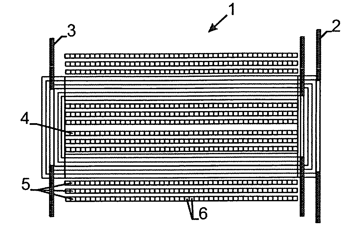
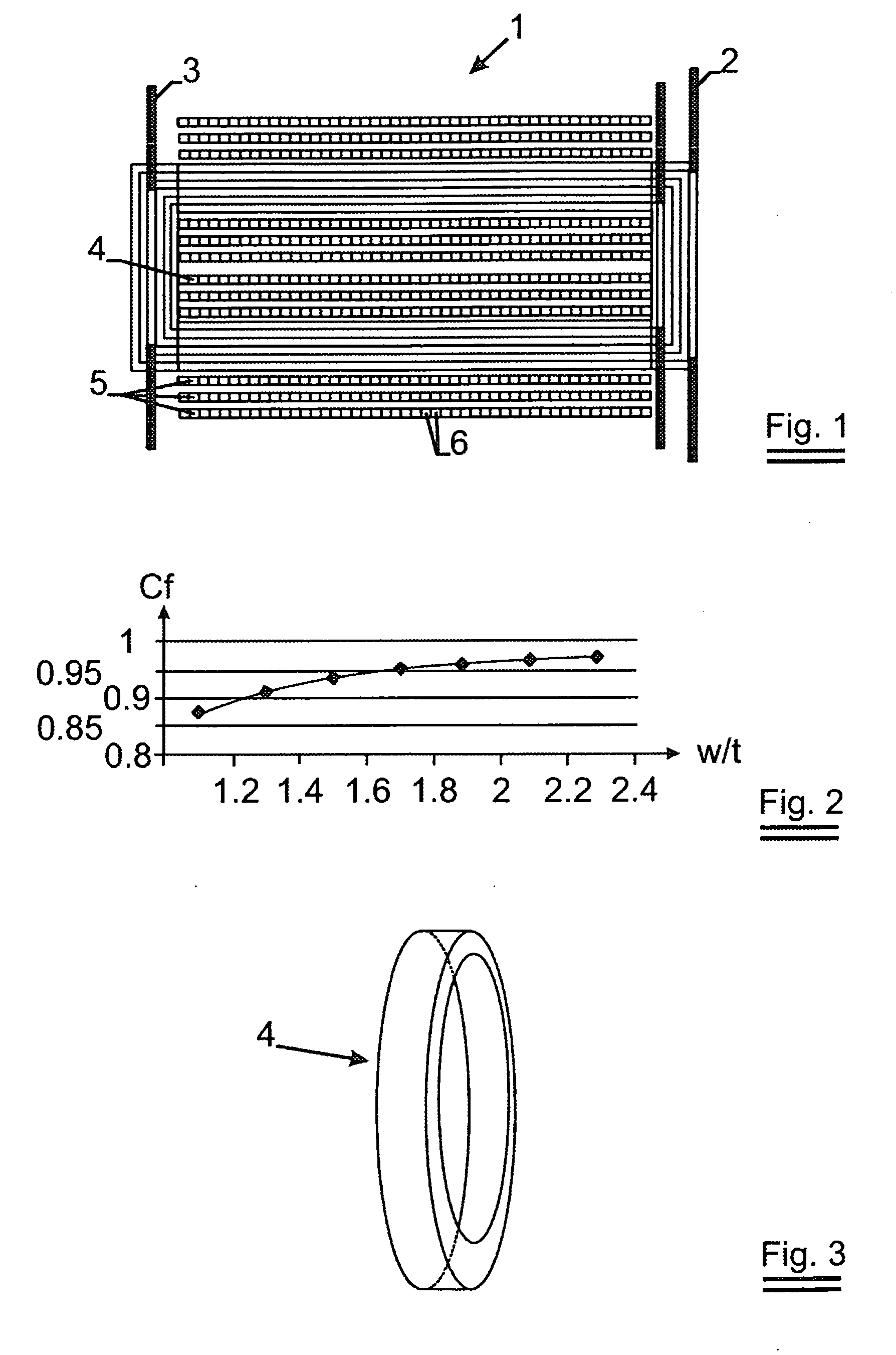
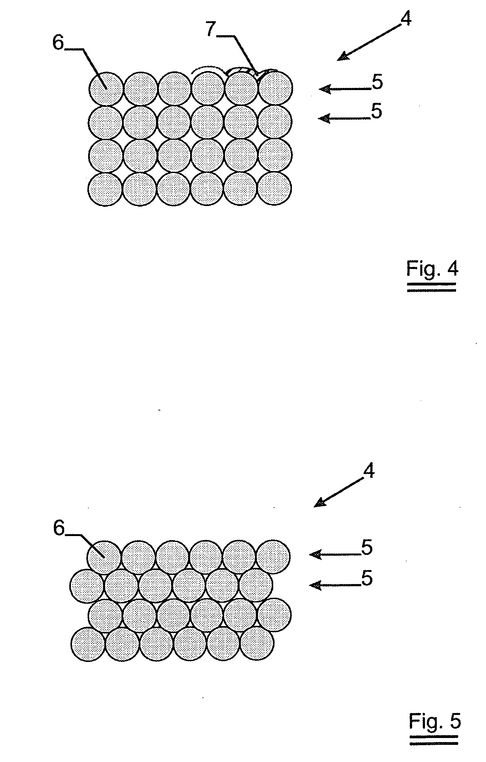
[0022]Turning now to FIG. 1, a schematic longitudinal cross section through a transformer 1 shown. The transformer 1 comprises e.g., the primary winding 2, the secondary windings 3 and the magnetic core 4. As can be seen from FIG. 1, the whole magnetic core 4 is built up by several superimposed layers 5 of adjacent windings of magnetic wire 6, whereby the cross section of each wire 6 is substantially rectangular. It is clear, that the compactness of the formed magnetic wire core 4 is very high thanks to the use of such wires 6 with a substantially rectangular cross section. However, by rolling or drawing the wires 6 into a rectangular shape, the edges of the wire are radiused. The higher the ratio width over thickness of each wire cross section is, the less rounding off of the wire edges and thereby the higher possible compactness is obtained.

[0023]FIG. 2 shows a graph illustrating the relation between the dimensions (width over thickness) of a rectangular cross section wire 6 and t...


PUM

PropertyMeasurementUnit
Electrical conductoraaaaaaaaaa
Magnetismaaaaaaaaaa

Abstract

Method of forming a magnetic core or part of a magnetic core including several layers of windings of magnetic wire in a very compact configuration, and the core or part of core is formed by winding several layers of a collated band of wires side by side until desired number of layers of core or part of core is obtained. Method includes forming magnetic core or magnetic flux return path or part of magnetic core including several layers of windings of magnetic wire in compact configuration; core or part of core being formed by winding several layers of a collated band of wires side by side until reaching desired number of layers of the core or part of the core. Magnetic core or magnetic flux return path includes several layers of windings of magnetic wire in compact configuration; part of layers of windings being formed by collated band of wires.

Description

CROSS-REFERENCE TO RELATED APPLICATIONS[0001]This application is a continuation of application no. PCT / EP2007 / 052113, filed Mar. 7, 2007, which claims the priority of European patent application no. 06075829.9, filed Mar. 30, 2006, and each of which is incorporated herein by reference.FIELD OF THE INVENTION[0002]This invention relates to a method of forming a magnetic core or part of a magnetic core comprising several layers of windings of magnetic wire in a closed compact configuration.BACKGROUND ART[0003]By magnetic wire is understood magnetically conducting wire or wire with magnetic properties, particularly with a high magnetic permeability, such as used e.g. for manufacturing a magnetic flux return path, such as the magnetic core of transformers, induction coils, electric motors, et cetera.[0004]The idea of replacing stacked sheets or plates of the magnetic core of a transformer by magnetic wires is already known. This is e.g., described in the following patent documents: Canad...

Claims


Application Information

Patent Timeline
IPC IPC(8): H01F7/06
CPCH01F3/06Y10T29/49Y10T29/4902H01F41/0206
Inventor MARRECAU, WILLYSTOCKEMER, JOELLE
Owner NV BEKAERT SA
Why Eureka
Try Eureka