Robotic Bypass System and Method

a robotic bypass and robotic technology, applied in the direction of electric cable suspension arrangement, overhead line/cable accessories, adjusting/maintaining mechanical tension, etc., can solve the problem of no mechanical test, and such tests would not be convenient with prior art equipmen

Inactive Publication Date: 2009-04-16
BARTHOLD LIONEL O
View PDF3 Cites 43 Cited by
  • Summary
  • Abstract
  • Description
  • Claims
  • Application Information

AI Technical Summary

Benefits of technology

[0017]In another application, one which serves only an electrical purpose, one end of the robotic bypass device can be made to grip an energized and current-carrying high voltage conductor while the other end grips a separate high voltage conductor which may be energized or un-energized. In this embodiment the electrical path provided by the robotic bypass device may be open by virtue of an insu

Problems solved by technology

Normally no mechanical test is made of the splice once it's insta

Method used


Image

  • Robotic Bypass System and Method
  • Robotic Bypass System and Method
  • Robotic Bypass System and Method

Examples


Embodiment Construction

I. Mechanical & Electrical Bypass Functions

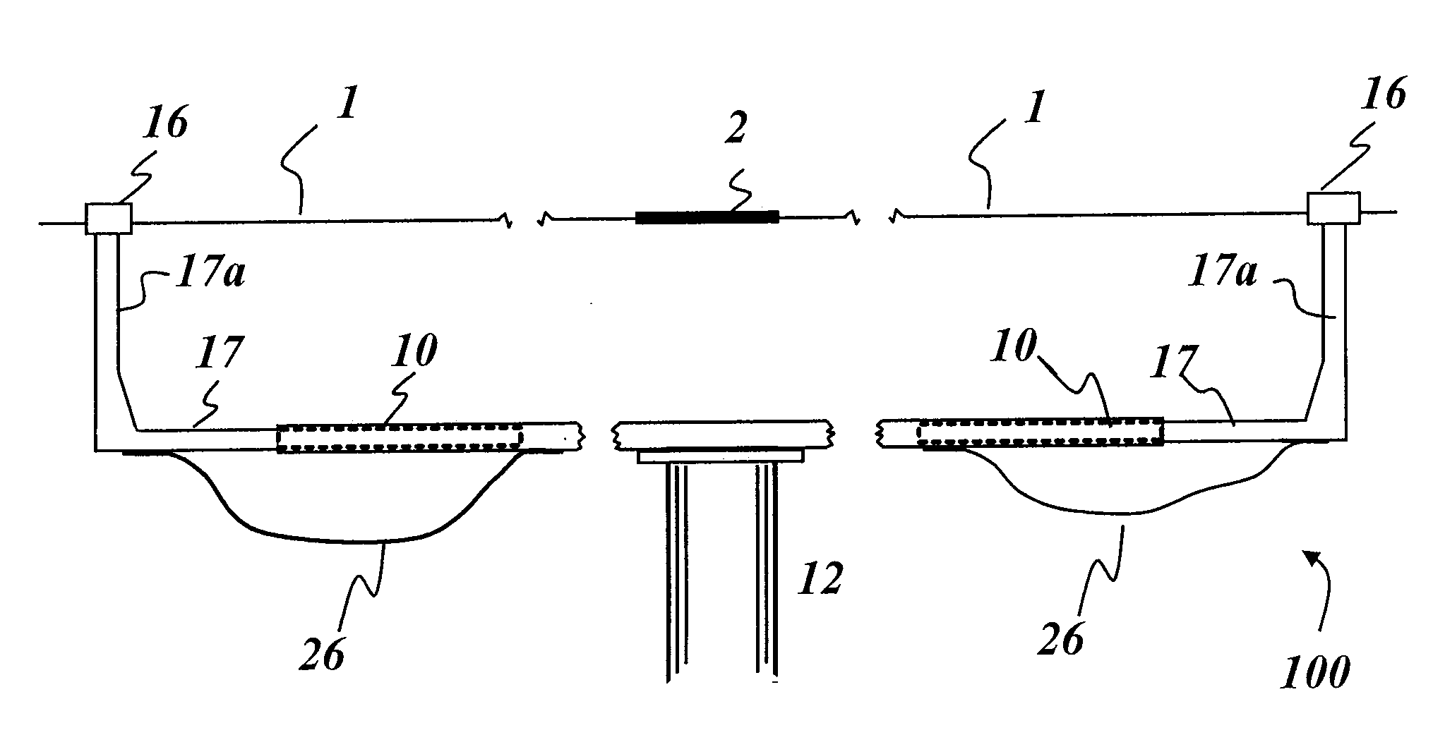
[0049]FIG. 10 is a simplified schematic of an embodiment of the inventive robotic bypass device 100, in this case mounted on an insulated boom, the robotic bypass device being adjustable in length hydraulically from a remote point. The mounting of the device on the insulated boom 12 is shown in simplified form, recognizing that adjustment and tilting capability of a boom-mounted device is known in the art and thus not shown in detail here, but could be incorporated in the robotic bypass device mounting mechanism. Also, the robotic bypass device could be incorporated into a helicopter-mounted platform, or could be supported by the high voltage line conductor itself. In FIG. 10 the robotic bypass device is positioned to grip the existing conductor 1 at points which straddle a defective splice 2. That positioning can be done from the ground, from a separate insulated bucket carrying the repair crew and hoisted to the same working location, or ...


PUM


Abstract

A system and method, and robotic equipment for mechanical and/or electrical bypassing of short sections of energized high voltage line conductors by gripping the conductor at two close-by points, making good electrical and mechanical connection, then drawing the two points towards one another so as to relieve both mechanical and current-carrying duty of the bypassed conductor section. Doing so can provide slack on the bypassed conductor section for maintenance or repair while simultaneously providing an alternative path for electric current, or increase tension on the adjacent conductor sections by essentially shortening the conductor in the region where the invention is applied. The invention may then reverse direction, placing (stretch) tension on the bypassed conductor section and the point of repair to assure its mechanical integrity. Mechanical bypassing only to temporarily shorten specific conductor spans may be achieved by the same device. Electrical bypassing only may be achieved in a similar manner by gripping and bridging two separate high voltage conductors, thus providing a means to connect and/or disconnect them with the aid of switching equipment incorporated into the invention. The invention allows all of the foregoing to be accomplished at line potential and in close line proximity by virtue of its being mounted on an insulated boom or suspended from a hovering helicopter or suspended from the line itself.

Description

CROSS REFERENCE TO RELATED APPLICATION[0001]This application claims priority of Provisional Application Ser. No. 60 / 979,454, filed on Oct. 12, 2007. The entire contents of this prior application are incorporated herein by reference.FIELD OF THE INVENTION[0002]This invention pertains to the installation of electrical cables or conductors onto towers of high voltage electric power lines.BACKGROUND OF THE INVENTION[0003]Maintenance and refurbishment of high voltage conductors is often done while a transmission line or substation remains in service. “Live-line” maintenance is usually achieved by lifting an enclosed platform (“bucket”) containing one or two linemen up to the conductors on an insulated boom. If the bucket is brought close to and electrically connected to a live high voltage conductor, it will assume the same potential as that of the conductors. Workers can make direct hands-on contact with the high voltage conductor and its associated hardware to make repairs without inju...

Claims


Application Information

Patent Timeline
IPC IPC(8): H02G7/05
CPCH02G1/04
Inventor BARTHOLD, LIONEL O.
Owner BARTHOLD LIONEL O
Why Eureka
Try Eureka