Systems and methods for cell balancing

Active Publication Date: 2009-04-16
O2 MICRO INC
View PDF8 Cites 37 Cited by
  • Summary
  • Abstract
  • Description
  • Claims
  • Application Information

AI Technical Summary

Problems solved by technology

A voltage difference between the cells may increase as the number of charging/discharging cycles increases, which may cause imbalance between the cells and may shorten a battery life.
During a time period when th

Method used


Image

  • Systems and methods for cell balancing
  • Systems and methods for cell balancing
  • Systems and methods for cell balancing

Examples


Embodiment Construction

[0013]Reference will now be made in detail to the embodiments of the present invention. While the invention will be described in conjunction with these embodiments, it will be understood that they are not intended to limit the invention to these embodiments. On the contrary, the invention is intended to cover alternatives, modifications and equivalents, which may be included within the spirit and scope of the invention as defined by the appended claims.

[0014]Furthermore, in the following detailed description of the present invention, numerous specific details are set forth in order to provide a thorough understanding of the present invention. However, it will be recognized by one of ordinary skill in the art that the present invention may be practiced without these specific details. In other instances, well known methods, procedures, components, and circuits have not been described in detail as not to unnecessarily obscure aspects of the present invention.

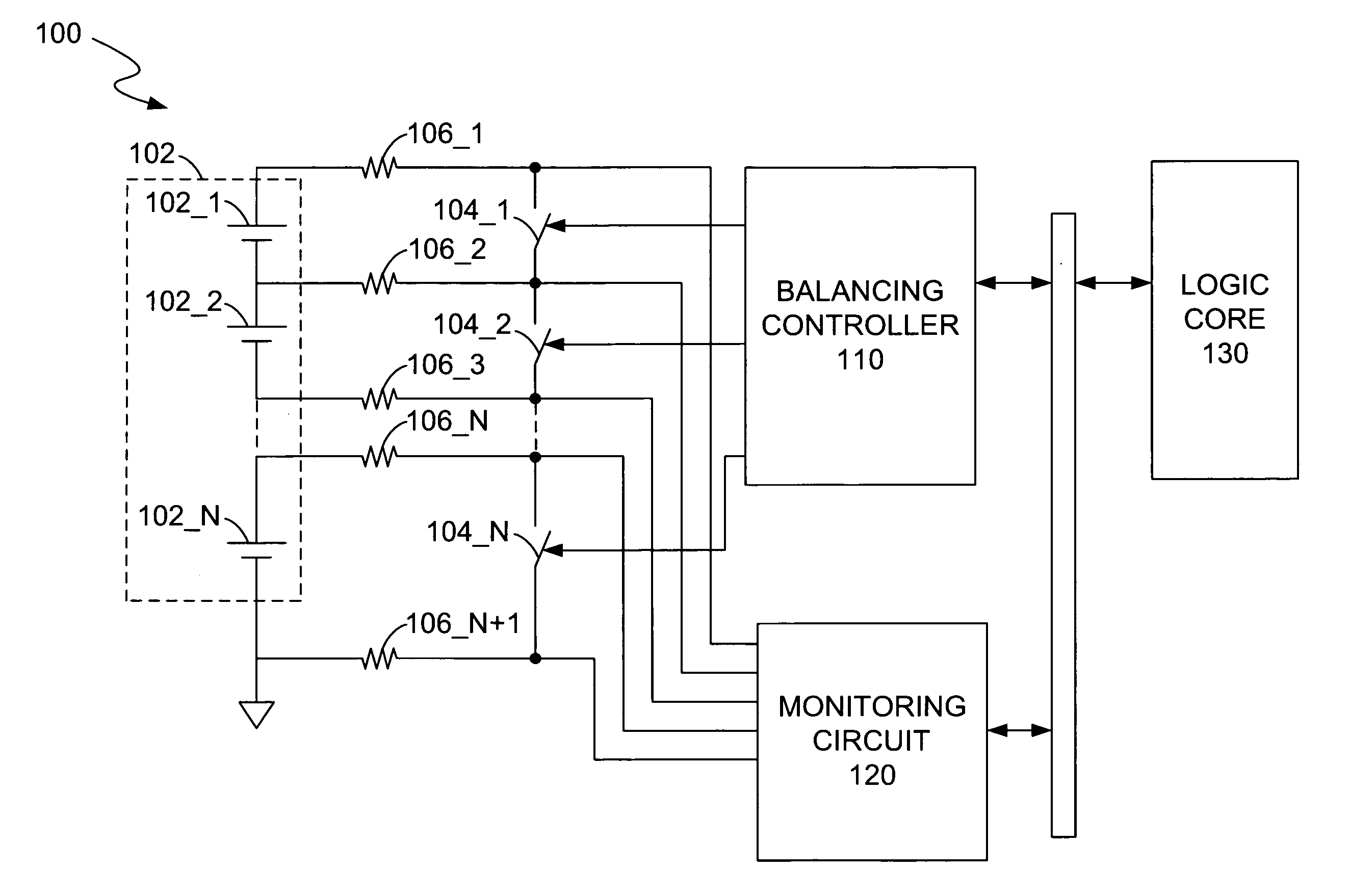
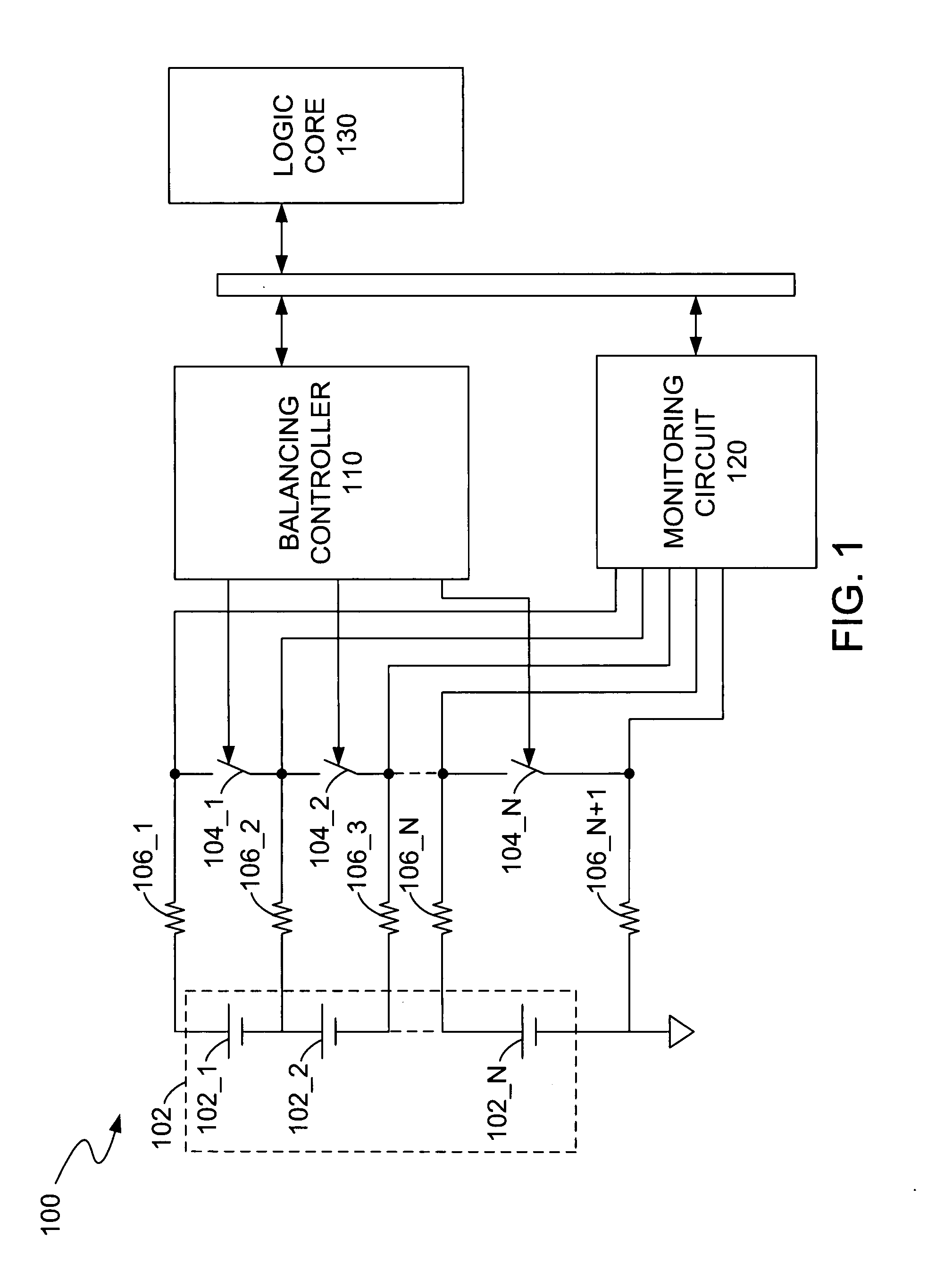
[0015]FIG. 1 shows a block ...


PUM


Abstract

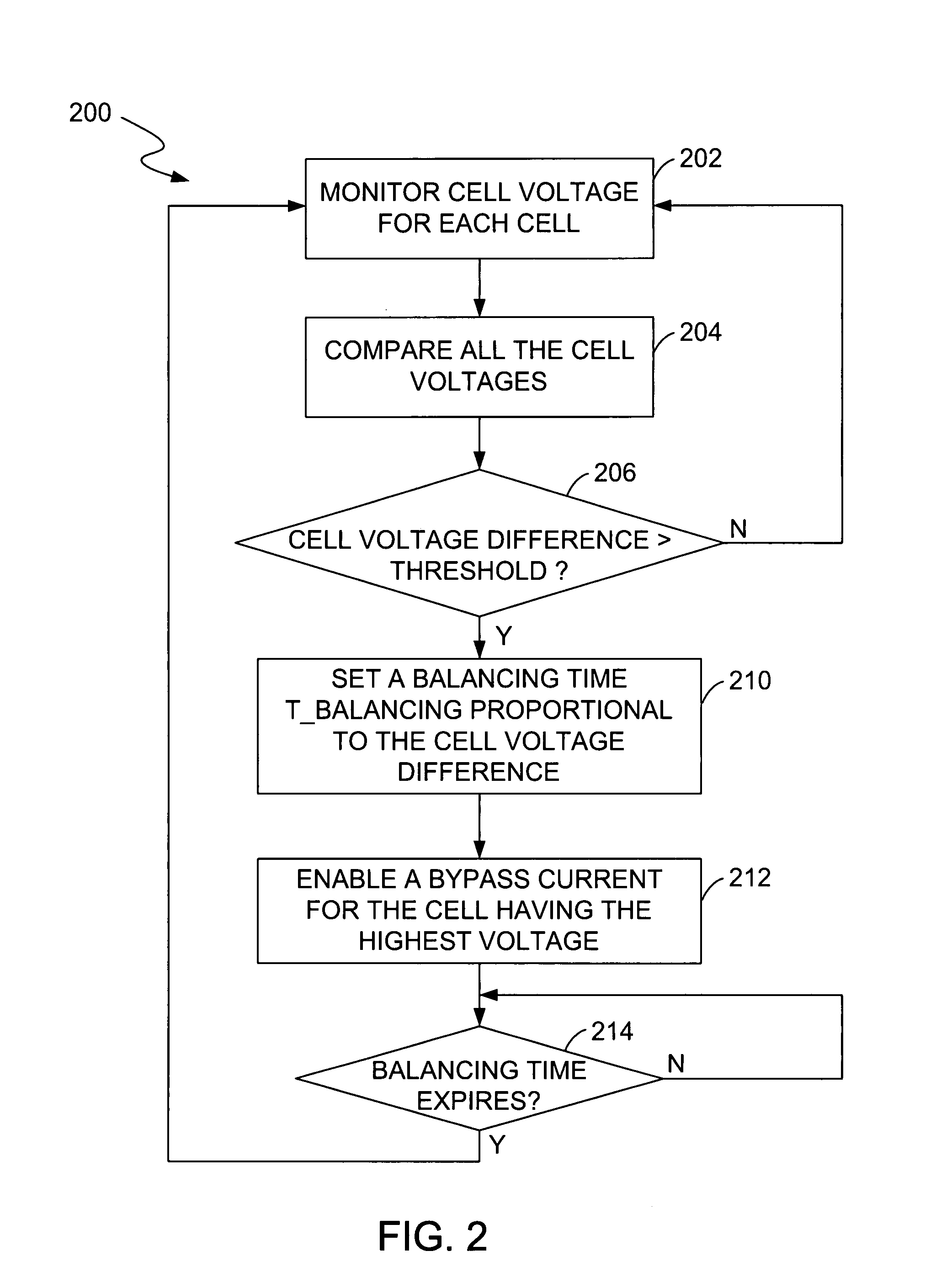
A cell balancing circuit comprises a first cell having a first voltage, a second cell in series with the first cell and having a second voltage that is greater than the first voltage, and a bypass path in parallel with the second cell for enabling a bypass current for the second cell if a difference between the first voltage and the second voltage is greater than a predetermined threshold. The bypass current is enabled for a balancing time period that is proportional to the difference between the fist voltage and the second voltage.

Description

RELATED APPLICATION[0001]This application is a continuation-in-part of the co-pending U.S. application filed on Sep. 25, 2007, entitled “Systems and Methods for Cell Balancing”, by inventors Flavius Lupu, Constantin Bucur, Xiaojun Zeng, Kaiyi Sheng, and Anquan Xiao, docket number 02-0414, which is hereby incorporated by reference in its entirety.TECHNICAL FIELD[0002]This invention relates to a battery protection system, and more particularly to a cell balancing system.BACKGROUND ART[0003]In a multi-cell battery pack, cells may differ from each other due to cell aging and different cell temperatures. A voltage difference between the cells may increase as the number of charging / discharging cycles increases, which may cause imbalance between the cells and may shorten a battery life.[0004]During a time period when the battery pack is discharged with a relatively high current, if the imbalance between the cells reaches a certain limit, a voltage reversal on the weakest cell may result in...

Claims


Application Information

Patent Timeline
IPC IPC(8): H02J7/00
CPCH02J7/0016
Inventor LUPU, FLAVIUSBUCUR, CONSTANTINZENG, XIAOJUNSHENG, KALYIXIAO, ANQUAN
Owner O2 MICRO INC
Why Eureka
Try Eureka