Signal compressing system

Inactive Publication Date: 2009-04-16
SAMSUNG ELECTRONICS CO LTD
View PDF32 Cites 28 Cited by
  • Summary
  • Abstract
  • Description
  • Claims
  • Application Information

AI Technical Summary

Problems solved by technology

However, the scanning regime of the aforementioned method does not take account of differences in the spectrum of

Method used


Image

  • Signal compressing system
  • Signal compressing system
  • Signal compressing system

Examples


Embodiment Construction

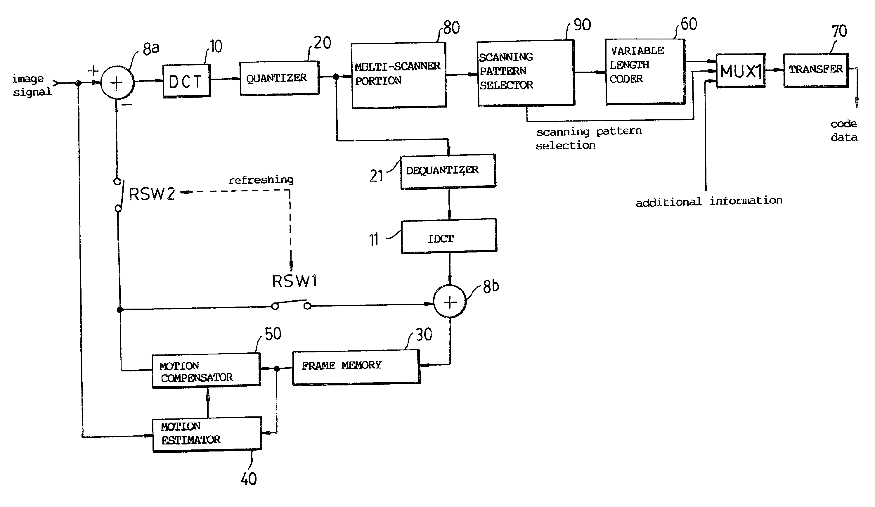
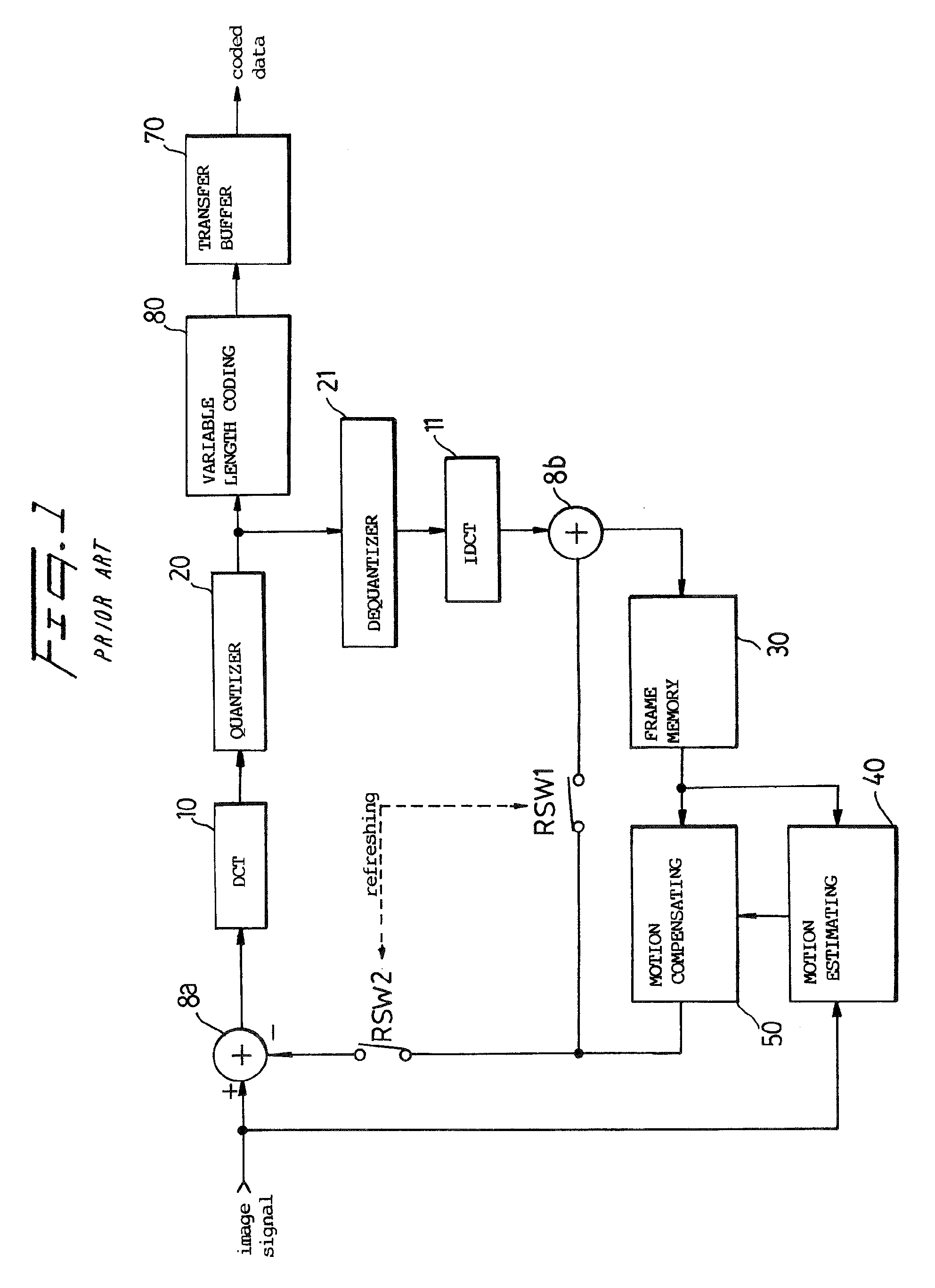
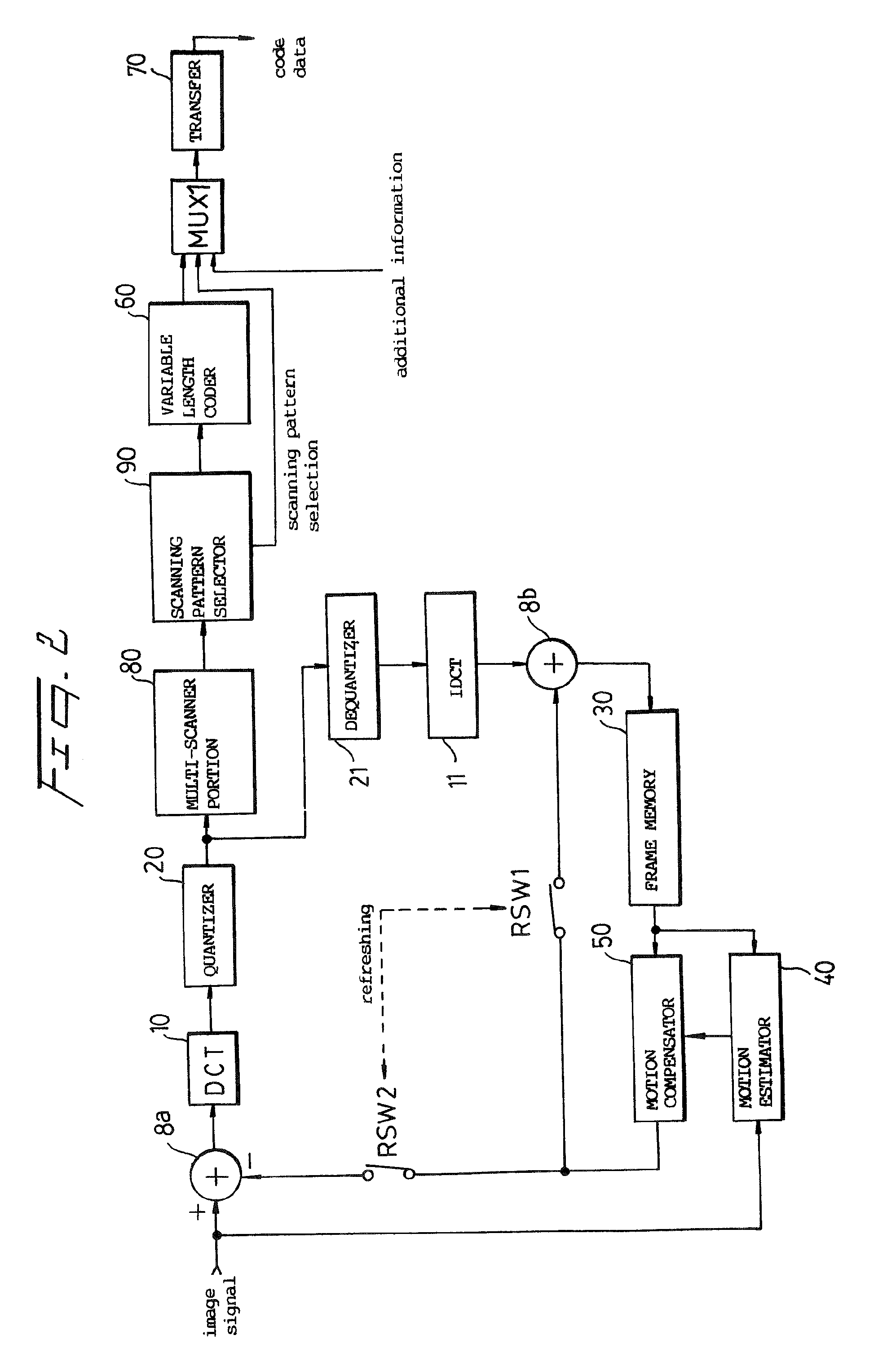
[0022]Referring to FIG. 2, an input signal is divided into equal-sized sub-blocks, for example, 8×8, 16×16, . . . . A motion estimator 40 determines a motion vector by comparing the current frame and a one frame delayed signal from a frame memory 30.

[0023]The motion vector is supplied to a motion compensator 60 which, in turn, compensates the delayed frame signal for movement. A first adder 8a produces a difference signal representing the difference between the present frame and the delayed, motion-compensated frame. A DCT coder 10 DCT-codes the difference signal. The DCT coded image signal is quantized by a quantizer 20 and then dequantized by a dequantizer 21. The dequantized signal is supplied to a second adder 8b, via IDCT 11, which adds it to the output of the motion compensator 11. This produces a signal corresponding to the original image signal.

[0024]The output of the motion compensator 50 is applied to the adders 8a, 8b by refresh switches RSW2 and RSW1, respectively.

[0025]...


PUM


Abstract

A multi-scanner scans a signal according to several different patterns. A scanning pattern selector determines which scanning pattern produced the most efficient coding result, for example, for runlength coding, and outputs a coded signal, coded most efficiently, and a selection signal which identifies the scanning pattern found to be most efficient.

Description

CROSS-REFERENCES TO RELATED PATENT APPLICATIONS[0001]This is a Continuation Application of application Ser. No. 11 / 873,282, filed Oct. 16, 2007; which is a Continuation Application of application Ser. No. 10 / 612,013, filed Jul. 3, 2003, and issued on Nov. 6, 2007, as U.S. Pat. No. 7,292,657; which is a Continuation Application of application Ser. No. 09 / 703,649, filed Nov. 2, 2000, and issued Jan. 20, 2004, as U.S. Pat. No. 6,680,975; which is a Continuation Application of application Ser. No. 08 / 024,305, filed Mar. 1, 1993, and issued on Jul. 17, 2001, as U.S. Pat. No. 6,263,026; the disclosures of which are incorporated herein by reference. One (1) Reissue application Ser. No. 10 / 609,438, filed on Jul. 1, 2003, of U.S. Pat. No. 6,263,026 has been abandoned. Continuation Application No. 12,338,647, filed Dec. 18, 2008 is a Continuation Application of 11 / 873,282, filed Oct. 16, 2007.FIELD OF THE INVENTION[0002]The present invention relates to a signal compressing system. A system ac...

Claims


Application Information

Patent Timeline
IPC IPC(8): H04N11/02H03M7/30G06T9/00H04N1/41H04N7/26H04N7/30H04N7/32H04N7/50
CPCH04N19/176H04N19/46H04N19/15H04N19/18H04N19/61H04N19/146H04N19/152H04N19/129H04N19/625
Inventor JEONG, JE-CHANGMUN, HEN-HEE
Owner SAMSUNG ELECTRONICS CO LTD
Why Eureka
Try Eureka