Image data compression apparatus for compressing both binary image data and multiple value image data

a compression apparatus and image data technology, applied in the field of image processing apparatuses, can solve the problems of large hard disk space, large memory capacity, and large cos

Active Publication Date: 2005-09-06
RICOH KK
View PDF13 Cites 21 Cited by
  • Summary
  • Abstract
  • Description
  • Claims
  • Application Information

AI Technical Summary

Benefits of technology

[0022]It is a general object of the present invention to provide an improved and useful image data compression apparatus in which the above-mentioned problems are eliminated.

Problems solved by technology

However, there is a large amount of information of an image, and if the image information is stored in a memory as it is, a large memory capacity is needed.
Since the unit price of a memory is high, a whole cost must become comparatively high and must use a large hard disk.
However, this method has a problem in that a context memory needed for the QM-coder as an arithmetic encoder and a line memory for producing a context require large-scale hardware and it is difficult to achieve a high-speed operation.
However, since assignment of a shorter repetition code may increase a run length which does not incident relatively, it is difficult to obtain the code set having a sufficient compression rate with respect image data of which color frequently changes at a short interval.
Moreover, the code set disclosed in Japanese Laid-Open Patent Application No. 9-65147 is similar to the MH coding, and it is difficult to expect a high-speed operation since a large number of gates is required when a plurality of bits are processed in parallel.
Accordingly, the above-mentioned image encoding method can achieve a high compression rate for a specific image, but it is difficult to achieve a sufficient compression rate for image data having frequent color change at a short interval.
Thus, there is a problem in that the scale of the hardware, a number of gates and the scale of software for achieving such data compression and encoding process are large.

Method used


Image

  • Image data compression apparatus for compressing both binary image data and multiple value image data
  • Image data compression apparatus for compressing both binary image data and multiple value image data
  • Image data compression apparatus for compressing both binary image data and multiple value image data

Examples


Embodiment Construction

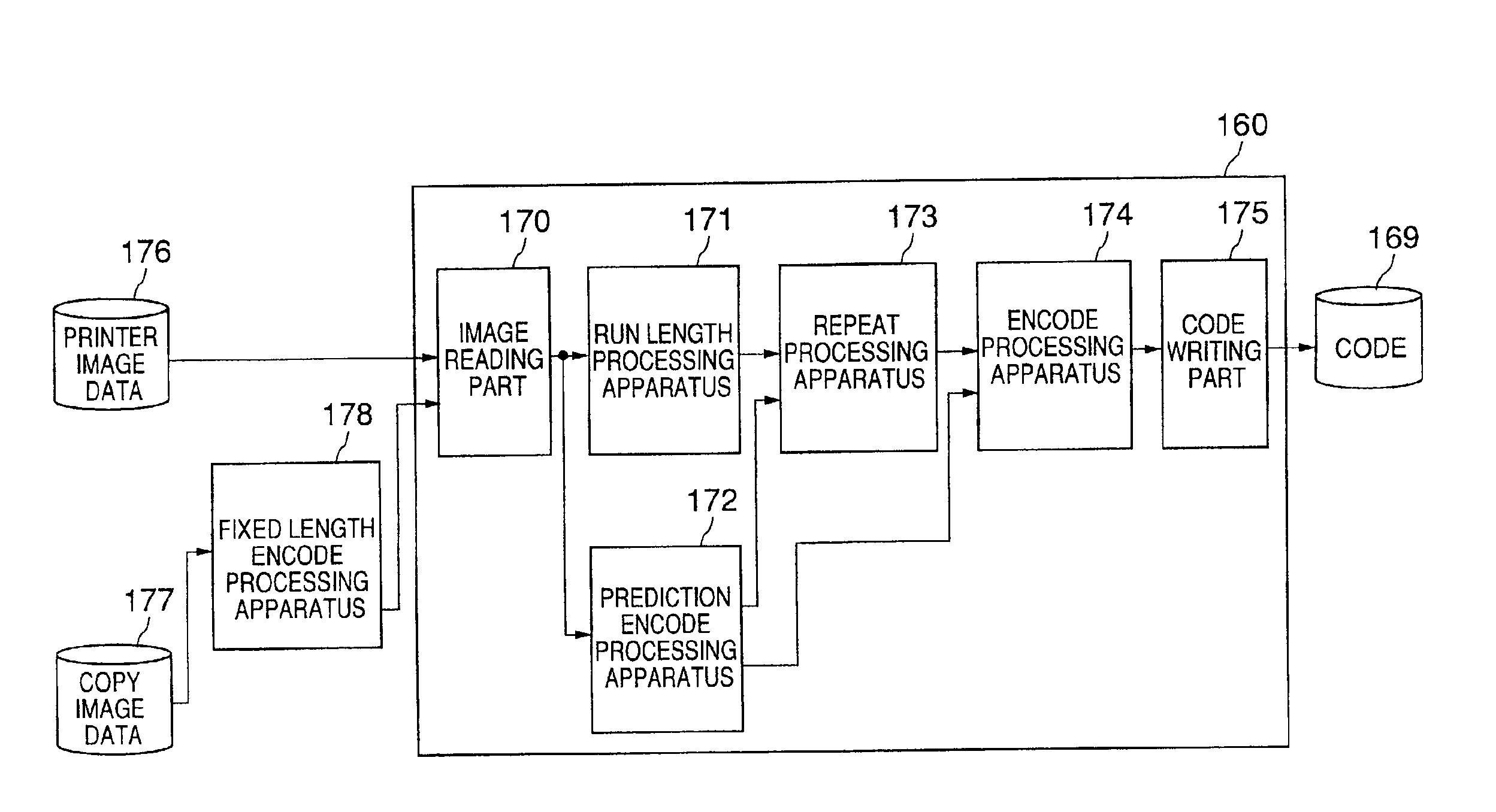
[0071]A description will now be given, with reference to the drawings, of an image data compression apparatus according to a first embodiment of the present invention.

[0072]FIG. 6 is an illustration of an image forming apparatus (digital copy machine) equipped with an image data compression apparatus according to an embodiment of the present invention. In FIG. 6, a bundle of original documents is placed on a manuscript table 102 of an automatic document feeder (hereinafter, referred to as ADF) with an image surface of each of the original documents facing upward. When a start key of an operational section is pressed, the original documents are sequentially fed to a predetermined position of a contact glass 105 by a feed roller 103 and a feed belt 104 one after another from the lowermost sheet of the original documents.

[0073]After reading an image of each of the original document on the contact glass 105 by a reading unit (scanner) 106, the original documents are ejected by a feed be...


PUM


Abstract

An image data compression apparatus which compresses code data obtained by compressing image data by a fixed length encoding method so as to reduce a scale of hardware and reduce a development cost of software for an image data compression a binary image data processing part processes binary image data in accordance with a run length encoding method, the binary image data processing part including an encoding part which encodes run lengths of the binary image data by an encoding part. A multiple value image data processing part processes multiple value image data in accordance with a prediction encoding method. The encoding part of the binary image data processing part is commonly used by the multiple image data processing part so that the encoding part compresses both the binary image data and the multiple value image data.

Description

BACKGROUND OF THE INVENTION[0001]1. Field of the Invention[0002]The present invention relates to image processing apparatuses for compressing and decompressing digital data or binary image data and, more particularly, to an image processing apparatus such as a digital copy machine, a scanner or a printer, which uses an encoding and decoding system appropriate for a memory saving mechanism to save a frame buffer capacity.[0003]2. Description of the Related Art[0004]An image data compression technique is generally used in an image processing field so as to reduce a capacity of a memory for storing image data, or reduce a transmission time of image data. Various approaches are used for image data compression according to processing mode of the image data. When carrying out a printing process of image data, it is required to perform a high speed process such as printing an image after rotating the image on a memory having a limited capacity. For this reason, a fixed length compression m...

Claims


Application Information

Patent Timeline
Patent Type & Authority Patents(United States)
IPC IPC(8): G06T9/00H03M7/46H04N1/419H04N1/41H04N1/413H04N1/417H04N19/107H04N19/159H04N19/192H04N19/34H04N19/423H04N19/50H04N19/93
CPCG06T9/004G06T9/005H03M7/46H04N1/41H04N1/419H04N19/93
Inventor SHIRAISHI, NAOTO
Owner RICOH KK
Why Eureka
Try Eureka