System and method for tracing cable interconnections between multiple systems

a technology of multiple systems and cable interconnections, applied in the field of communication networks, can solve the problems of high cost of space in these environments, complex network deployment and upgrade challenges for providers, and real possibility of incorrect connections, and achieve the effect of reducing the time taken

Active Publication Date: 2009-04-16
ALCATEL LUCENT SAS
View PDF24 Cites 41 Cited by
  • Summary
  • Abstract
  • Description
  • Claims
  • Application Information

AI Technical Summary

Benefits of technology

[0019]Another advantage of the invention is that it reduces the time taken to troubleshoot cabling interconnection problems of communications equipment, both electrical and optical interconnections, as well as other types of electronic systems in general.
is that it reduces the time taken to troubleshoot cabling interconnection problems of communications equipment, both electrical and optical interconnections, as well as other types of electronic systems in general.

Problems solved by technology

This evolution presents significant challenges to service and network providers, which attempt to serve their clients faster and better, by continuously enlarging and upgrading their networks with a view to serve a growing number of client and to implement the latest advances in networking technologies.
Because the cost of space in these environments is high, the equipment is commonly organized in the most compact manner that is practical.
As a result, there is often a confusing collection of cabling running through the environment to interconnect the equipment within the respective location (office, cabinet, etc.) to both other equipment within the location and equipment outside of the location.
In particular, network deployment and upgrading present complex challenges to providers, one of which is interconnection between equipment (also referred to here as systems) of various sizes, makes and functionality that made-up the network.
These techniques would also apply to cabling connections of electronic systems in general, in situations where there are numerous systems to be interconnected at a particular installation site and there is a very large number of electrical or optical cables interconnecting-them, such that there exists a very real possibility of incorrect connections.
In these cases, determining the exact nature of any interconnection errors would be a very onerous and time consuming task.
However, physical tags may become separated from the cables and the labels may be rendered illegible.
Further, locating a particular tag amongst a great many tagged cables in a crowded environment may be difficult.
Further, designing and manufacturing unique connectors for a very large number of cables is difficult and relatively costly because each can only serve a particular function and production runs tend to be in relatively small numbers.
However, not only does this solution require an OSS or NMS capable of receiving and processing the interconnection information, it also requires that all systems participating in this solution have RFID readers at their port connectors.
Retrofitting or replacing the I / O cards of legacy systems to include the required RFID readers may not be practical or cost-effective in many cases.
In summary, the above solutions are not cost-effective when applied to legacy systems or when an OSS / NMS is not present in the network, or it is present but it does not support the respective solutions.
However, this solution is mostly concerned with locating the equipment in case of faults and does not address the problem of correctly connecting the cables to the equipment at a certain location.

Method used


Image

  • System and method for tracing cable interconnections between multiple systems
  • System and method for tracing cable interconnections between multiple systems
  • System and method for tracing cable interconnections between multiple systems

Examples


Embodiment Construction

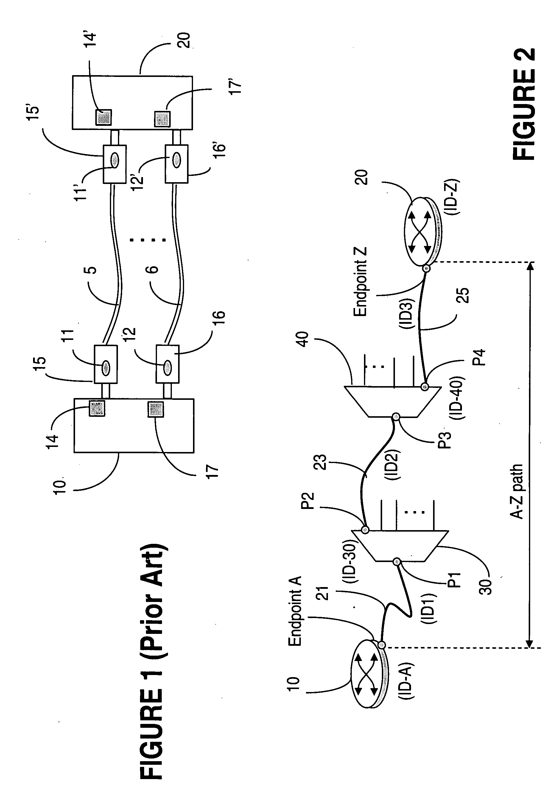
[0026]FIG. 1 (Prior art) illustrates one of the current solutions used for tracing cabling interconnections using radio frequency identification tags. In this example, cables 5 and 6 operatively connect two units of equipment 10 and 20. A RFID pairs of tags 11, 11′ and 12, 12′ are affixed proximate to each end of the cables 5 and respectively 6. Preferably, the tags are embedded in the respective connector 15, 15′ and 16, 16′ mounted at the end of the respective cables 5 and 6. The tags store cable identity data that distinguishes the cables from each other, distinguishes the ends of the cables, and identify the equipment and ports the cables should connect to. The identity data may include additional data to specify further information about the cable or the connector, etc. For example, in the case of an optical fiber cable, the additional data may indicate the fiber type so that the properties for a laser that will be used to produce signals transmitted on the fiber may be selecte...


PUM


Abstract

Techniques to ascertain physical cabling connections of electronic systems are provided for situations where there are numerous systems interconnected by a very large number of electrical or optical cables. A cable identifying code is inserted into a message sent from a local endpoint system to remote endpoint system over the identified cable. Each intermediate system that is in the interconnection path between the two endpoint systems of interest appends its code for the cable connected to the I / O port from which the message will egress that system and be sent to the next system along the path. The remote endpoint system receives the message which now contains codes for all the cables transited along the path, extract the codes, and thereby determines the exact cabling used in the interconnection of the two endpoint systems.

Description

FIELD OF THE INVENTION[0001]The invention is directed to communication networks and in particular to a system and method for tracing cabling interconnections between multiple systems.BACKGROUND OF THE INVENTION[0002]Evolution of network technologies resulted in a world of interconnected networks where businesses and households are now amazingly close to each-other. The notion of “network” turns out to be central to our times: the Internet, LANs, WANs, enterprise networks, home networks, etc. are today interconnected over the World Wide Web, changing our lives and the way we do business. This evolution presents significant challenges to service and network providers, which attempt to serve their clients faster and better, by continuously enlarging and upgrading their networks with a view to serve a growing number of client and to implement the latest advances in networking technologies.[0003]Typically, the equipment making up these networks is situated in environmentally hardened enc...

Claims


Application Information

Patent Timeline
Patent Type & Authority Applications(United States)
IPC IPC(8): G06F11/00
CPCG06F11/006
Inventor LANGE, ANDREW SNOWDENNELSON, SCOTT WILIAM
Owner ALCATEL LUCENT SAS
Why Eureka
Try Eureka