Device for Illumination and Insect Extermination

a technology for insect extermination and illumination, applied in the field of insect traps, can solve the problems of unfavorable large volume of insects living and in plain view, and affecting the appearance of insects, so as to achieve the effect of preventing the transmission of power to the grid

Inactive Publication Date: 2009-04-23
PRATER ADRIAN
View PDF17 Cites 55 Cited by
  • Summary
  • Abstract
  • Description
  • Claims
  • Application Information

AI Technical Summary

Benefits of technology

[0018]By ensuring that a path of light is left unobstructed by the grid, the device is more effective at serving as an illumination source as well as an insect exterminator.
[0019]Preferably there is provided a switch connected between the electrical connectors and the light source for selectively preventing and allowing transmission of the power from said electrical connectors to said light source. Preferably the switch is a photoelectric sensor for preventing and allowing transmission of the power to the

Problems solved by technology

This feature limits where these devices can be placed and the wraparound arrangement of the grid about the light source interferes with light emitted therefrom, making the devices suitable for killing insects but not for doubling as a useful light source.
The substantially closed arrangement of the trap does not allow enough light to escape the body to add a useful secondary illuminating function to the primary insect trapping function.
The trap

Method used


Image

  • Device for Illumination and Insect Extermination
  • Device for Illumination and Insect Extermination
  • Device for Illumination and Insect Extermination

Examples


Embodiment Construction

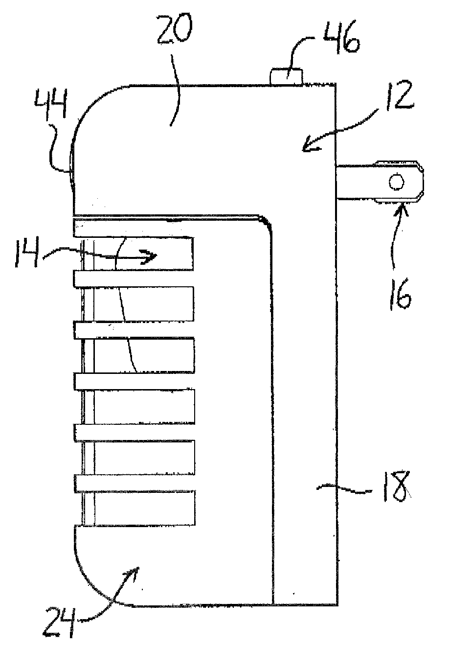
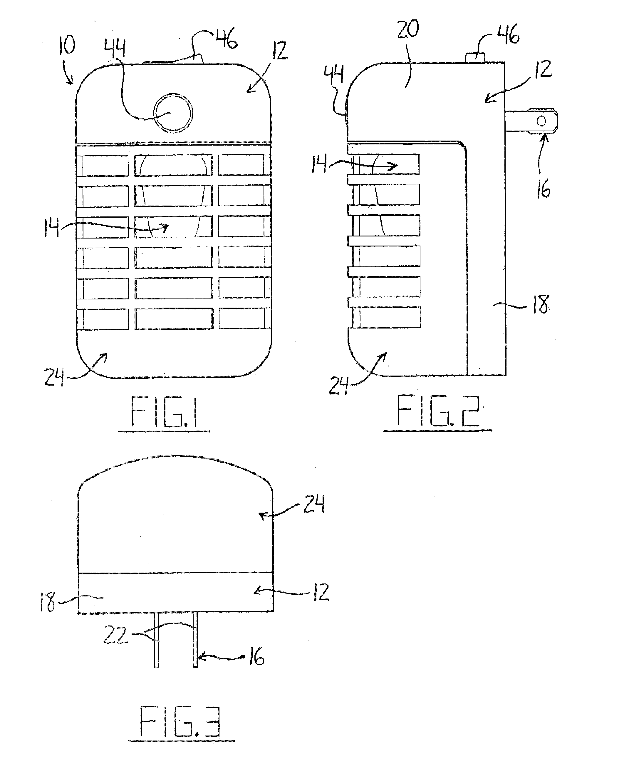
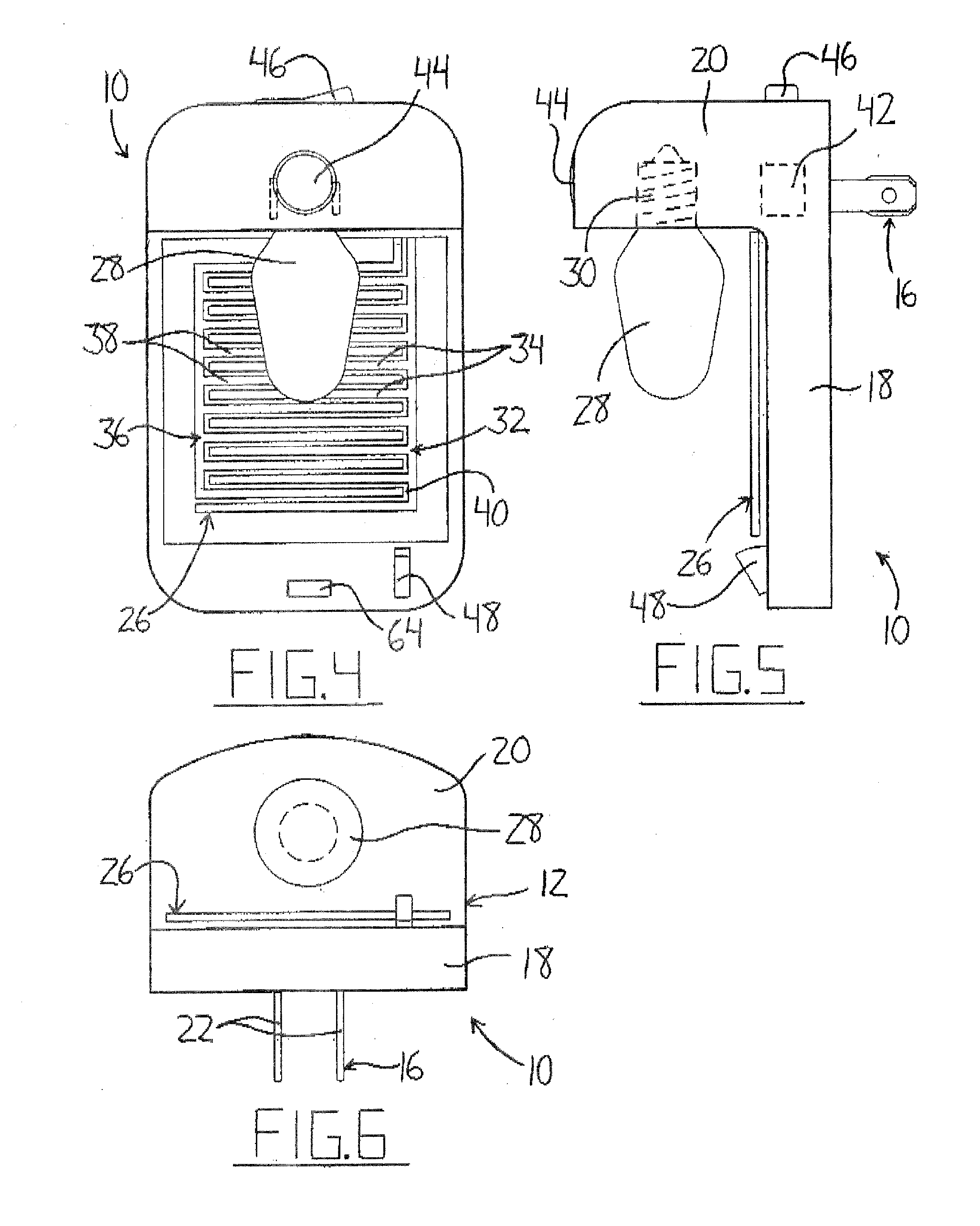
[0041]FIGS. 1 to 3 illustrate a fully assembled device for illumination and insect extermination according to the present invention. The device 10 used for both the extermination of insects and the illumination of darkened areas is shown having a construction designed for mounting in a generally flush arrangement with a typical household electrical wall outlet. The device 10 includes a housing 12 that supports a light source 14 and electrical connectors 16. The housing features a vertically extending mounting portion 18 that sits flush against a wall when a pair of prongs 22 forming the electrical connectors 16 extending rearward from the mounting portion 18 are inserted into a wall mounted electrical outlet to provide power to the device 10 and support it on the wall. A protruding portion 20 extending horizontally outward from the mounting portion 18 in a direction opposite the prongs 22 supports the light source 14. A guard 24 is detachably mounted on the housing 12 beneath the pr...


PUM


Abstract

A device for illumination and insect extermination for use with a conventional electrical wall outlet features a light source and an electrocution grid both operatively connected to electrical connectors through which power is supplied. The light source and grid are arranged such that the grid does not interfere with the transmission of light in at least one direction. A housing and a perforated translucent guard positioned about the light source and grid allow a substantial portion of the light emitted to leave the device while preventing accidental human contact with the electrocution grid. A switch allows the grid to be manually disabled while removal of the guard causes automatic disabling. A photoelectric sensor prevents wasteful energy use by activating the light source only when the surrounding environment is substantially dark.

Description

[0001]This application claims the benefit under 35 U.S.C. 119(e) of U.S. provisional application Ser. No. 60 / 733,196, filed Nov. 4, 2005.FIELD OF THE INVENTION[0002]This invention relates to an insect trap, and more particularly to an insect trap having a light source used to attract insects.BACKGROUND OF THE INVENTION[0003]It is often desirable to set out insect traps to either kill or restrain insects that have invaded human occupied territory, especially within the home. A number of devices have been developed that attract insects to such traps by means of electrically produced light.[0004]U.S. Pat. Nos. 1,962,420 and 4,951,414 both disclose insect electrocuting devices having high voltages applied across spaced apart electrodes such that insects that make their way between the electrodes act as a pathway for electricity to travel through to complete a circuit. In each case, the insects are attracted to this electrocution grid by a light source around which the grid is disposed. ...

Claims


Application Information

Patent Timeline
IPC IPC(8): A01M1/22A01M1/04
CPCA01M1/04A01M2200/012A01M1/223
Inventor PRATER, ADRIAN
Owner PRATER ADRIAN
Why Eureka
Try Eureka