Traveling Vehicle

Inactive Publication Date: 2009-04-23
YANMAR CO LTD
View PDF66 Cites 6 Cited by
  • Summary
  • Abstract
  • Description
  • Claims
  • Application Information

AI Technical Summary

Benefits of technology

[0026]According to the present invention, with regard to a traveling vehicle comprising an engine supported on a body frame and a fuel tank between the engine and a seat for supplying fuel, the fuel tank is disposed below a steering wheel and below a vertical middle portion of a dashboard.
[0027]Accordingly, the space in the lower portion of the dashboard or below the dashboard can be used effectively. The fuel tank can be arranged at the comparative low position without lowering the minimum ground clearance of the traveling vehicle, whereby fuel can be supplied easily from an oil supply tank to the fuel tank.
[0028]Apart or all of the fuel tank is covered by a part of the dashboard when viewed in side.
[0029]Accordingly, the space in the lower portion of the dashboard or below the dashboard can be used effectively. The fuel tank can be arranged at the comparative low position without lowering the minimum ground clearance of the traveling vehicle, whereby fuel can be supplied easily from an oil supply tank to the fuel tank.
[0031]Accordingly, the space in the lower portion of the dashboard or below the dashboard can be used effectively. The fuel tank can be arranged at the comparative low position without lowering the minimum ground clearance of the traveling vehicle, whereby fuel can be supplied easily from an oil supply tank to the fuel tank.

Problems solved by technology

However, the position of the fuel filler of the fuel tank becomes comparatively high and it is necessary to hang up an oil supply tank high for supplying fuel to the fuel tank.
Accordingly, in the case that a heavy thing such as a working machine is attached through an elevating link to the rear portion of the traveling vehicle, the whole traveling vehicle becomes unbalance.
With regard to the third structure disposing the fuel tank below the step, the minimum ground clearance of the traveling vehicle is lowered so that the lower portion of the traveling vehicle may interfere with and damage crops.

Method used


Image

  • Traveling Vehicle
  • Traveling Vehicle
  • Traveling Vehicle

Examples


Embodiment Construction

[0086]Explanation will be given on an embodiment of the present invention.

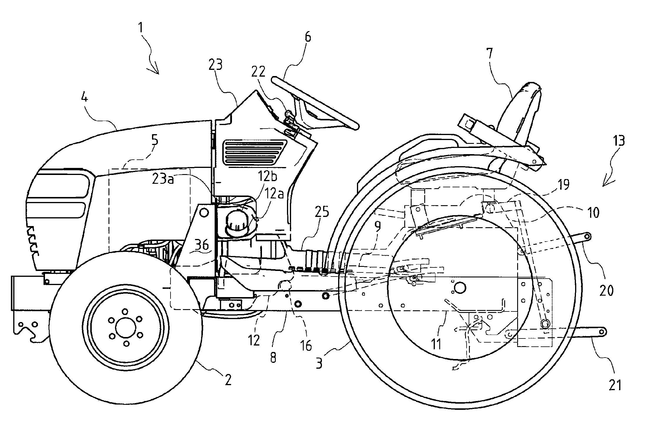
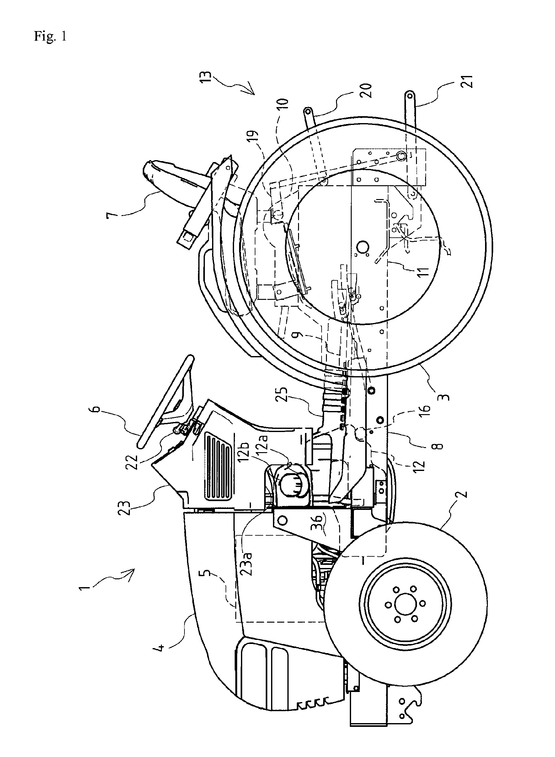
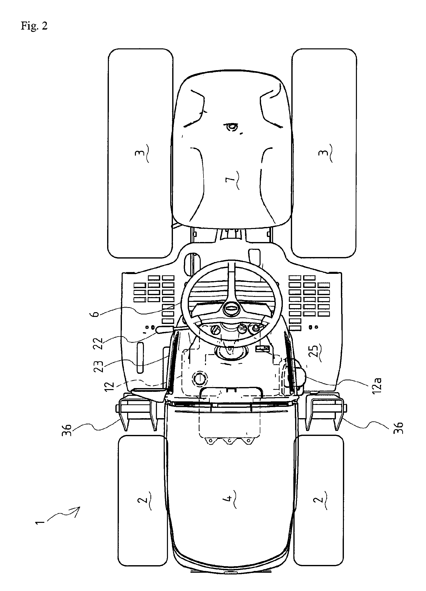
[0087]FIG. 1 is a left side view of entire construction of a tractor 1 according to an embodiment of a traveling vehicle of the present invention. FIG. 2 is a plan view of the same. FIG. 3 is a side view of another embodiment of positional relation between a fuel tank 12 and a dashboard 23. FIG. 4 is a perspective rear view of the vicinity of the fuel tank 12. FIG. 5 is a rear view of the fuel tank 12. FIG. 6 is a side view of the same. FIG. 7 is a plan view of the same. FIG. 8 is a perspective upper rear view of the fuel tank 12. FIG. 9 is a perspective upper rear view of support construction of the fuel tank 12. FIG. 10 is a perspective lower rear view of support construction of the fuel tank 12.

[0088]Firstly, explanation will be given on the entire construction of the tractor 1 according to the embodiment of the traveling vehicle of the present invention.

[0089]As shown in FIGS. 1 and 2, with regard to the t...


PUM


Abstract

The purpose of the present invention is to make supply of fuel to a fuel tank easy without making the fuel tank interfere with a drive shaft or a front wheel drive shaft and without lowering minimum ground clearance of a traveling vehicle.A fuel tank 12 is disposed between an engine 5 and a seat 7 and below a steering wheel 6, and a groove 12c is provided longitudinally at the substantial lateral center of the fuel tank 12. A power steering valve 24 is attached to the lower portion of the steering wheel 6, and grooves 12L and 12R in which hydraulic pipings 32 and 33 connected to the power steering valve 24 are arranged is formed in the fuel tank 12.

Description

TECHNICAL FIELD[0001]The present invention relates to a traveling vehicle such as a tractor. Especially, the present invention relates to shape and arrangement of a fuel tank mounted on a traveling vehicle and arrangement of a fuel filler of the fuel tank.BACKGROUND ART[0002]Conventionally, with regard to a traveling vehicle such as a tractor, there is well known structure that a fuel tank is disposed just before a steering wheel at an upper rear portion of a bonnet of the front portion of the traveling vehicle (for example, see the Patent Literature 1). There is also well known structure that a fuel tank is disposed at the rear end of the vehicle body between left and right rear wheels and before a seat (for example, see the Patent Literature 2).[0003]In resent, structure is proposed that a fuel tank is disposed below a step (for example, see the Patent Literature 3).[0004]Patent Literature 1: the Japanese Patent Laid Open Gazette Hei. 10-325373[0005]Patent Literature 2: the Japane...

Claims


Application Information

Patent Timeline
IPC IPC(8): B60K15/03
CPCB60K15/063F02M37/0094B62D5/062B60Y2200/221
Inventor MATSUMOTO, KUNIHIKO
Owner YANMAR CO LTD
Why Eureka
Try Eureka