Method for Production of Carbon Dioxide and Apparatus Therefor

a carbon dioxide and production method technology, applied in the direction of gaseous fuels, hydrogen sulfides, energy inputs, etc., can solve the problems of most detrimental environmental effects, achieve economic efficiency, minimize environmental damage, and supply easily

Inactive Publication Date: 2012-08-09
MPD TECH
View PDF8 Cites 9 Cited by
  • Summary
  • Abstract
  • Description
  • Claims
  • Application Information

AI Technical Summary

Benefits of technology

[0011]The economic utilization of solar thermal for electric power generation has long been recognized as a possible solution to the world's quest for an alternative form of energy. Several characteristics of solar energy provide unparalleled features that make solar power desirable as an energy source. Besides being the primary and ultimate source of most forms of naturally occurring energy used as a matter of course, solar and thermal energy is freely available in most areas of the world on a year round basis, is abundant, has economic efficiency and lacks most detrimental environmental effects, such as pollution and green house emissions and other harmful effects to the environment. Energy experts have opined that solar energy has the potential to easily supply all of the world's energy needs in manner that minimizes the harmful effects of environmental damage and is locally produced so that the economy is not impacted.

Problems solved by technology

Besides being the primary and ultimate source of most forms of naturally occurring energy used as a matter of course, solar and thermal energy is freely available in most areas of the world on a year round basis, is abundant, has economic efficiency and lacks most detrimental environmental effects, such as pollution and green house emissions and other harmful effects to the environment.

Method used


Image

  • Method for Production of Carbon Dioxide and Apparatus Therefor
  • Method for Production of Carbon Dioxide and Apparatus Therefor
  • Method for Production of Carbon Dioxide and Apparatus Therefor

Examples


Embodiment Construction

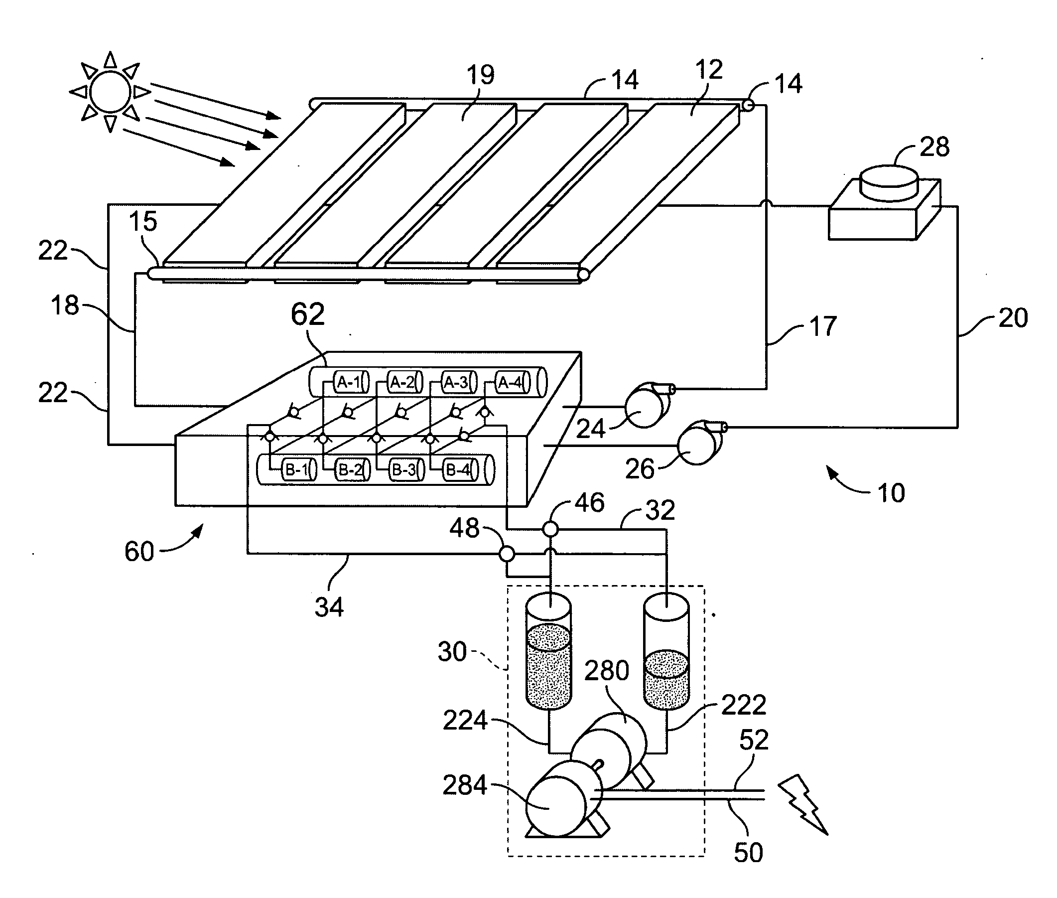
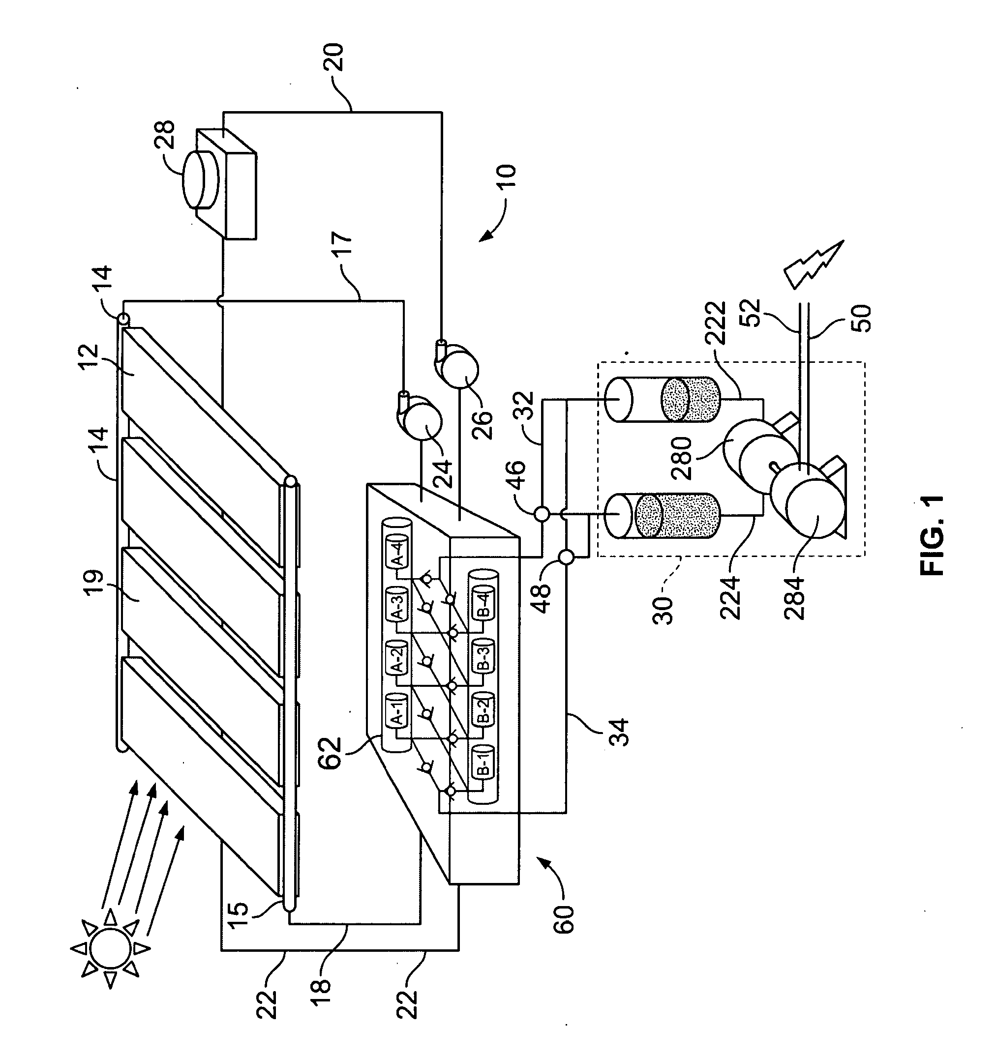
[0032]Referring now to FIG. 1, a multi-stage heat exchange system 10 according to the present invention is illustrated showing in schematic outline the elements of the system, with heat being provided in the form of radiation form the sun. The multi-stage heat exchange system comprises a solar hot water panel heat collector 12, which may be conventional, as shown. Alternatively, the collector may have characteristics that will enhance the energy collection efficiency or concentration, for example, such as that provided by solar energy collectors shown and described in U.S. Pat. No. 4,002,499 to Winston, as well as others.

[0033]The collector may comprise a simple array of pipes 17, 18, a transitional portion of which is embedded in a black, or solar energy absorbing, matrix 19, such as those used in conventional solar water heaters. A heat transfer fluid inflow pipe 17 permits water, or another heat transfer material, to flow into the solar collector 12 through a pipe manifold 14, as...


PUM

PropertyMeasurementUnit
temperatureaaaaaaaaaa
temperaturesaaaaaaaaaa
temperatureaaaaaaaaaa

Abstract

A system for conversion of waste and solar heat energy into a carbon sequestration device, including as a collector for collecting carbon dioxide gas from a carbon dioxide gas source, such as ambient air. The Joule Thompson effect is used to cool and thereby refrigerate / liquefy ambient air and then extracting carbon dioxide therefrom, comprising steps of and means for providing a hydride heat engine, operating the hydride heat engine utilizing hydride thermal compression technology to compress hydrogen gas and thereby to cool ambient air to a temperature rendering air into a refrigerated / liquefied state by use of a Joule-Thompson type process, and extracting carbon dioxide from the refrigerated / liquefied ambient air and collecting the carbon dioxide.

Description

CROSS REFERENCE TO RELATED APPLICATIONS[0001]This is a divisional of previously filed non-provisional application Ser. No. 12 / 345,192 filed on Dec. 29, 2008 and issued on Feb. 14, 2012 as U.S. Pat. No. 8,114,363, relying for priority on Provisional Application No. 61 / 009,474, filed on Dec. 29, 2007, which is a continuation in part of Ser. No. 12 / 053,279, which claims domestic priority to U.S. Provisional Patent Application Ser. No. 60 / 921,030 filed on Mar. 31, 2007, and pending U.S. Non-provisional application Ser. No. 11 / 209,161, filed on Aug. 22, 2005 and also is a continuation in part of U.S. patent application Ser. No. 11 / 644,693, filed Dec. 12, 2006, which is a non-provisional of Provisional Application No. 60 / 845,129, filed on Sep. 16, 2006 and of Provisional Application No. 60 / 854,278, filed on Oct. 25, 2006, all of which applications are incorporated by reference as if fully set forth herein.BACKGROUND OF THE INVENTION[0002]1. Field of the Invention[0003]This invention relat...

Claims


Application Information

Patent Timeline
Patent Type & Authority Applications(United States)
IPC IPC(8): F25J1/02B01J8/00C25B9/00
CPCC10L1/04C10L3/08C10L2290/42C01B3/0005Y02E60/324C25B1/04Y02E70/10Y02E60/366C10G2/32Y02E60/32Y02E60/36Y02P20/133
Inventor GOLBEN, P. MARK
Owner MPD TECH
Why Eureka
Try Eureka