Image recording device

Active Publication Date: 2014-09-18
SEIKO EPSON CORP
View PDF5 Cites 6 Cited by
  • Summary
  • Abstract
  • Description
  • Claims
  • Application Information

AI Technical Summary

Benefits of technology

The invention provides a way to efficiently cool a rotating drum in an image recording device that ejects liquid onto a recording medium. This is particularly important because the optical illuminator heats up the drum during curing, which can cause variations in the distance between the ejecting head and the drum. By using a certain configuration, the system can effectively cool the drum to prevent these issues.

Problems solved by technology

In such an image recording device, when the rotating drum is heated by a heat source located inside the device, the rotating drum thermally expands, and the distance between the rotating drum and the ejecting head varies, resulting in mispositioning of the liquid attached onto the recording medium.
On the other hand, only generation of an airflow by a fan located at one side of the drum, as described in U.S. Pat. No. 5,502,476, does not easily allow a large amount of an airflow to pass through the hollow portion of the rotating drum quickly, and efficient cooling of the rotating drum can be difficult in some cases.
Thus, a large amount of gas can be supplied to the hollow portion of the rotating drum.
In particular, since the optical illuminator applies light onto a portion of the recording medium wrapped around the rotating drum, the rotating drum is heated by heat generated during curing of the photocurable liquid to cause a problem of a variation of the distance between the rotating drum and the ejecting head.

Method used


Image

  • Image recording device
  • Image recording device
  • Image recording device

Examples


Embodiment Construction

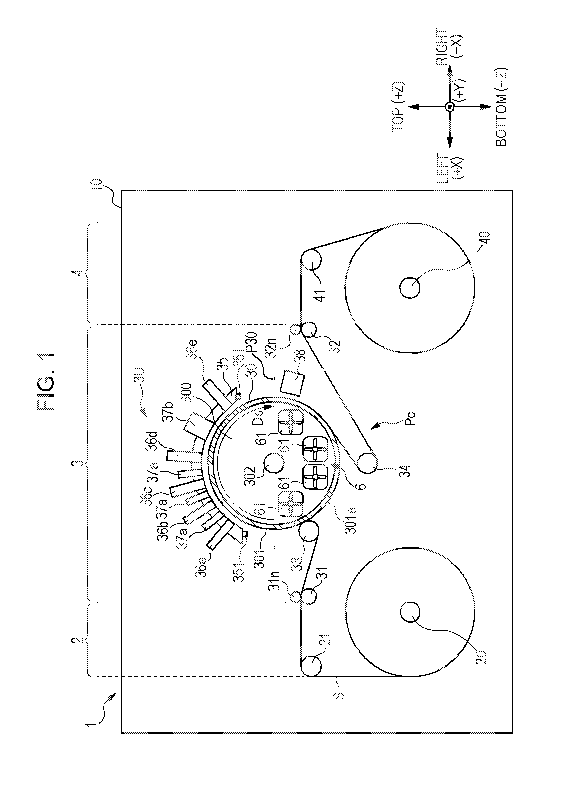
[0027]FIG. 1 is a front view schematically illustrating an outline of a configuration of a printer to which the invention is applicable. FIG. 1 and the following drawings employ an XYZ orthogonal coordinate system including a lateral direction X, a front-to-back direction Y, and a vertical direction Z of a printer 1 in order to clarify the positional relationship among components of the printer as necessary.

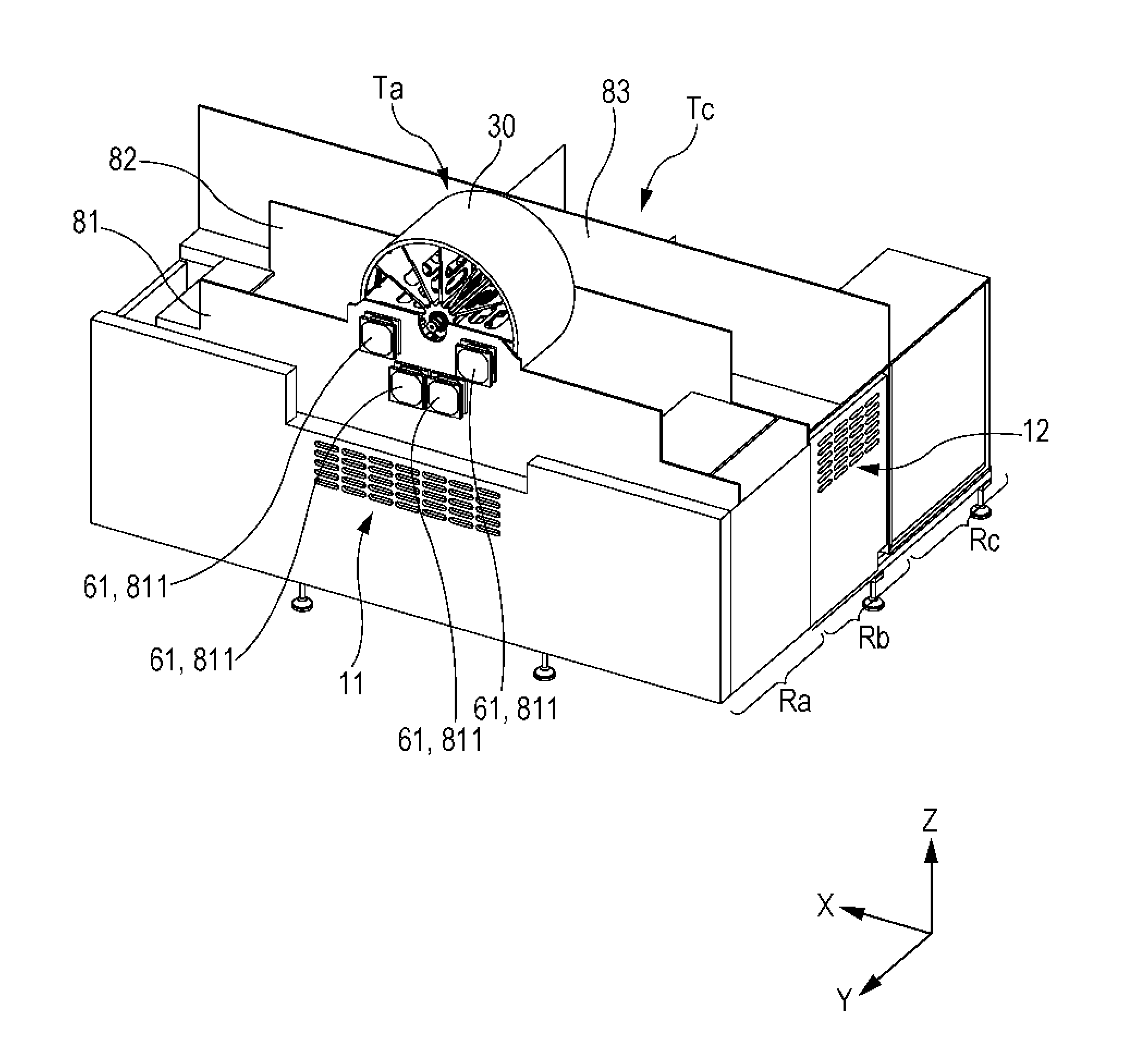
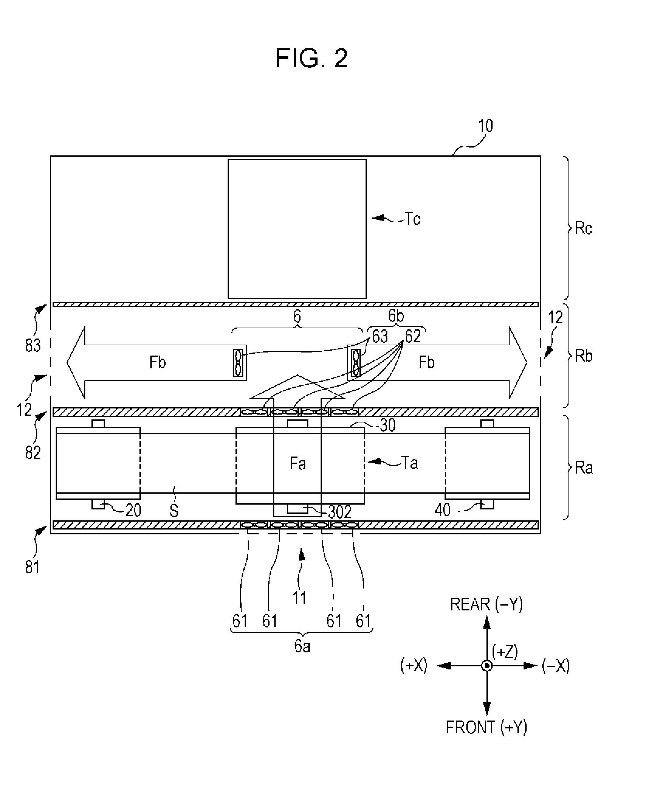
[0028]The printer 1 includes a feeder 2, a processor 3, and a winder 4 that are arranged along the lateral direction X and are housed in a housing 10 (an exterior member). The feeder 2 and the winder 4 include a feeder shaft 20 and a winder shaft 40, respectively. A sheet S (a web) is stretched between the feeder shaft 20 and the winder shaft 40 with the two ends of the sheet S being wound into a roll around the feeder shaft 20 and the winder shaft 40. Along a path Pc formed by the stretching, the sheet S is transported from the feeder shaft 20 to the processor 3, subjected to pr...


PUM


Abstract

An image recording device includes: a rotating drum configured to rotate and including a cylindrical hollow outer member having an outer peripheral surface around which a recording medium is wrapped during rotation of the rotating drum; an ejecting head facing the outer peripheral surface of the rotating drum and configured to eject liquid onto the recording medium wrapped around the outer peripheral surface of the rotating drum; an air supply unit configured to supply gas from one side of the rotating drum to a hollow portion surrounded by the outer member of the rotating drum in an axial direction along which a rotating shaft of the rotating drum extends; and an exhaust unit configured to exhaust gas from the hollow portion to the other side of the rotating drum in the axial direction.

Description

BACKGROUND[0001]1. Technical Field[0002]The present invention relates to an image recording device that ejects liquid from an ejecting head onto a recording medium supported on the outer peripheral surface of a rotating drum, and particularly to a technique for cooling the rotating drum.[0003]2. Related Art[0004]U.S. Pat. No. 5,502,476 describes a printer that ejects ink from a print head onto the outer peripheral surface of a drum so as to record an image. In this printer, ink on the drum is cooled and solidified by means of the drum, and then the ink is transferred to a print medium constituting a nip together with the drum, thereby printing an image on the print medium. To cool the ink by means of the drum effectively, the drum is cooled with an airflow generated by a fan. Specifically, the fan axially faces a hollow portion axially penetrating the drum, and generates an airflow that cools the drum while passing through the hollow portion (see FIG. 11).SUMMARY[0005]Another type o...

Claims


Application Information

Patent Timeline
IPC IPC(8): B41J11/00B41J11/04
CPCB41J11/04B41J11/0015B41J29/377
Inventor SUZUKI, MANABU
Owner SEIKO EPSON CORP
Why Eureka
Try Eureka