Wind generator for installation on a house

Inactive Publication Date: 2011-12-15
NGUYEN JIM
View PDF26 Cites 2 Cited by
  • Summary
  • Abstract
  • Description
  • Claims
  • Application Information

AI Technical Summary

Benefits of technology

[0008]The present invention is directed to a wind turbine / generator for installation on the roof of a house or other, typically small, business facility. The turbine is responsive to the flow of wind to generate electricity used in the house or facility in lieu of electricity delivered to the house or facility from a power grid operated by an electrical utility. This makes the home owner or business owner less dependent on the utility to supply his electrical energy needs. Conversely, the turbine diminishes the demand on the utility which makes it easier for the utility to supply the power requirements of its customers, particularly during times of peak energy demand.
[0009]The turbine comprises an assembly including a primary wind source and one or more secondary wind sources which are used to rotate a shaft on which elements of the turbine are installed. This improves the efficiency of the turbine to produce electricity. An advantage of the secondary wind sources is that they maintain shaft rotation, so the turbine produces electricity, even if the shaft is decoupled from the primary wind source during excessive wind speed conditions. This wind sources comprise housings mounted on the roof of a structure and rotatable with the wind to catch as much of the wind as possible and use it to produce shaft rotation.
[0010]The turbine further employs a series of magnets spaced about the turbine with the position of the magnets being controlled by the force of the wind. In addition, relatively cool air is directed through the magnets onto the turbine assembly to reduce the heat load produced by the turbine and further improve its efficiency.
[0012]Depending on the facilities, two or more generators can be arranged in rows or in-line. The generators are not only useful to supplement electricity supplied by a utility. In rural, remote, or undeveloped areas, the wind turbine provides a cheap, relatively constant source of electricity.

Problems solved by technology

As such, while these units are well suited for installations in industrial parks or the grounds of a factory or manufacturing facility, they are impractical for use for on a home site or small business facility.
Separate and apart from any aesthetics associated with installing a tall structure next to a house, for example, the cost to erect and maintain such a unit is probably prohibitive for most home owners and small business people.
Energy costs are increasing.
Further, in many rural, remote, or undeveloped areas, a constant supply of electricity is unavailable.
This is both expensive and requires a large amount of storage space.

Method used


Image

  • Wind generator for installation on a house
  • Wind generator for installation on a house
  • Wind generator for installation on a house

Examples


second embodiment

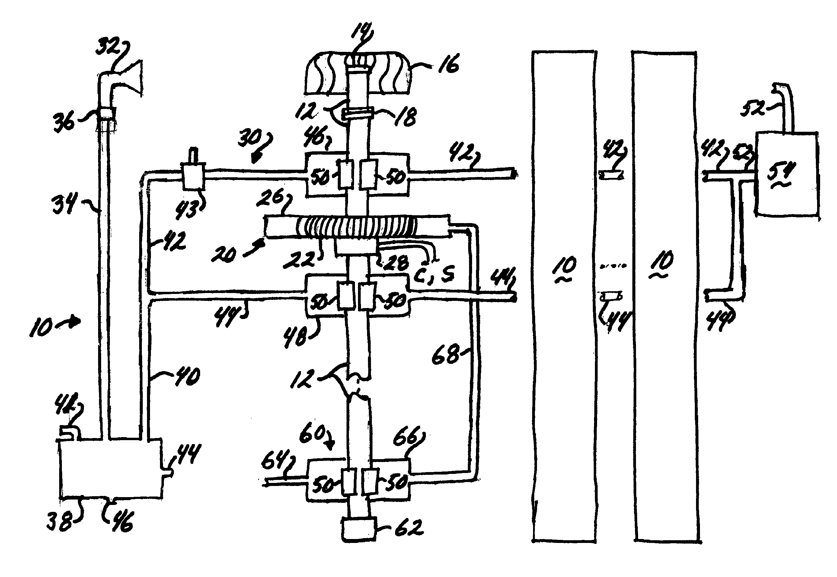
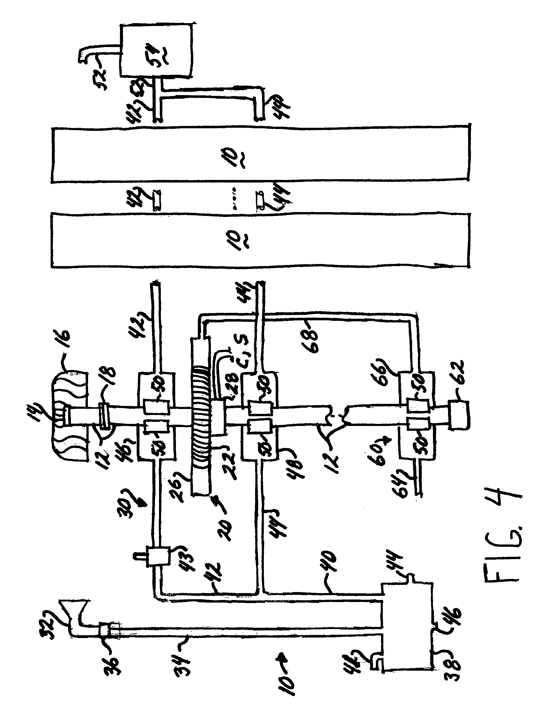
[0039]Referring now to FIG. 7, the wind turbine is indicated generally 100. Each turbine 100 includes a coupling 118 connecting an upper section of a shaft 112 connected to a housing 116, and a lower section of the shaft. As with the previously described embodiment, if the wind speed becomes so strong that damage may occur to either the shaft or the housing, coupling 118 disconnects the upper section of the shaft from the housing to prevent damage to the shaft. Again, when the wind speed abates coupling 118 reconnects the two sections of the shaft.

[0040]The electrical generator portion of wind turbine 100 is indicated generally 120 and includes a wire wound rotor 122 mounted on shaft 112 to rotate through an electromagnetic field established in conjunction with magnets housed in an assembly 126. The electric current is drawn off to converter C or storage unit S through a slip ring assembly 128. Again those skilled in the art will understand that the elements comprising electrical ge...

first embodiment

[0049]Finally, reciprocal air intakes 350 are installed about housing 330. These intakes draw air into the housing through a chamber 352 located at the surface of the water. Air drawn in through the intakes is directed to the magnet assembly within housing 330 for the same reasons as discussed with regard to the invention.

[0050]In view of the above, it will be seen that the several objects and advantages of the present disclosure have been achieved and other advantageous results have been obtained.


PUM


Abstract

Apparatus (10) for generating electricity comprises a plurality of wind turbines (20) each of which has a rotatable shaft (12) on which a rotor assembly (22) is mounted for turning about a magnet assembly (26). The shaft is coupled to a housing (16) which is rotated in response to wind flow to produce shaft rotation. A second mechanism (30) also produces shaft rotation in response to wind flow, whereby the wind turbine generates electricity in response to wind flow. While each wind turbine has its own shaft, housing, and coupling, the second mechanism is commonly connected to all the wind turbines. A third mechanism (60) is also provided for producing shaft rotation. Each wind turbine includes its own third mechanism. Other embodiments of the invention include a hybrid turbine (100) which utilizes both air and water to produce shaft rotation, and a submerged turbine (300).

Description

CROSS REFERENCE TO RELATED APPLICATIONS[0001]NoneSTATEMENT REGARDING FEDERALLY SPONSORED RESEARCH OR DEVELOPMENT[0002]N / ABACKGROUND OF THE INVENTION[0003]This invention relates to a wind turbine or wind generator for producing electricity; and, more particularly, to a generator for installation on the roof of a house or other small structure.[0004]Wind turbines or wind generators are known in the art. The typical wind generator comprises a multi-bladed propeller mounted atop a pole and the structure is often referred to as a windmill generator. The propeller rotates in response to wind currents and rotation of a shaft on which the propellers are mounted turn the rotor of an electrical generator and produce electricity. Although many such generators are located on wind farms so a large number of units located in close proximity to each other in a grid produce large amounts of electricity, individual units have been installed adjacent a facility to produce electricity used by the faci...

Claims


Application Information

Patent Timeline
IPC IPC(8): F03D9/00F03B13/00F03D11/00
CPCF03B17/063F03D9/002F05B2240/911Y02B10/30Y02E10/728Y02B10/70Y02E10/28Y02E10/725Y02B10/50F03D9/25Y02E10/20Y02E10/72F03D9/34F03D9/008F03D3/02
Inventor NGUYEN, JIM
Owner NGUYEN JIM
Why Eureka
Try Eureka