Aircraft nose gear control apparatus

Inactive Publication Date: 2009-04-23
ADAM AIRCRAFT INDUSTRIES +1
View PDF35 Cites 16 Cited by
  • Summary
  • Abstract
  • Description
  • Claims
  • Application Information

AI Technical Summary

Benefits of technology

[0004]In one aspect, the invention addresses the problems noted above and provides specific and general solutions to aircraft landing gear that control wheel rotation in order to prevent damage. In other aspects, the invention comprises an aircraft landing gear orientation locking device to restrict the rotational freedom of the nose gear wheel or wheels. The main stabilizing and control shaft of the landing gear has, at its upper region, an upper shaft connection arm that is connected to the shaft and is capable of being locked to restrict or prevent the arm's rotational movement. A second arm at the lower region of the shaft c

Problems solved by technology

In many airport settings, towing and moving of aircraft is often required by ground vehicles due to airport restrictions and space limitations.
However, due to the free rotation usually allowed for the forward gear when on the taxiway, the towing and pushing can cause damage to the gear itself.
Moreover, the inability to control t

Method used


Image

  • Aircraft nose gear control apparatus
  • Aircraft nose gear control apparatus
  • Aircraft nose gear control apparatus

Examples


Embodiment Construction

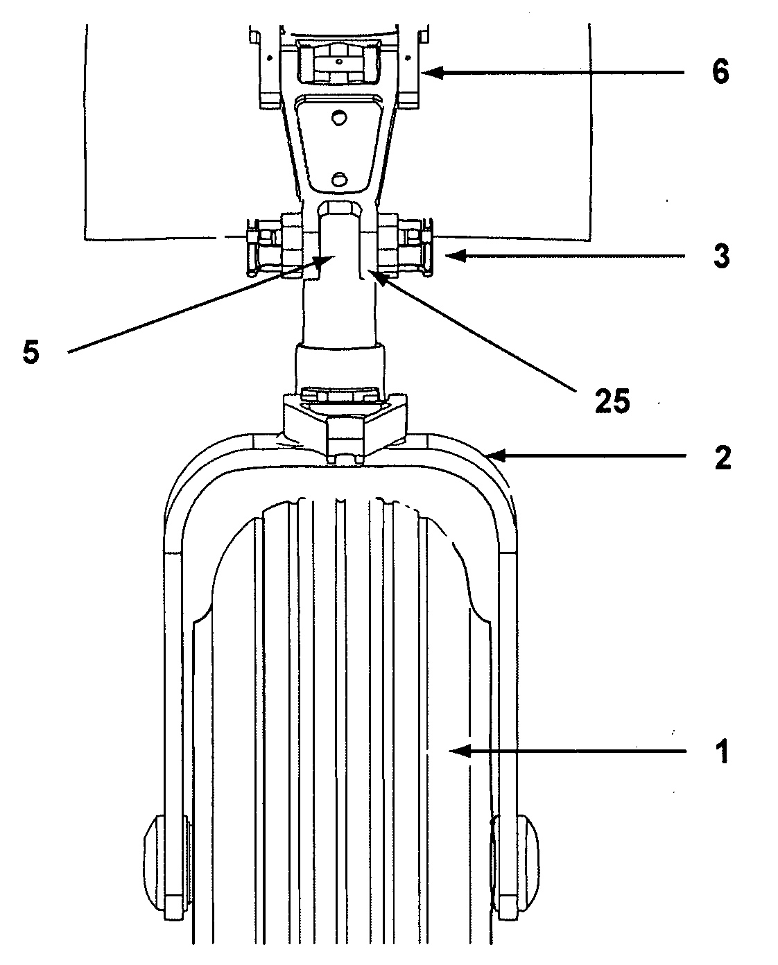
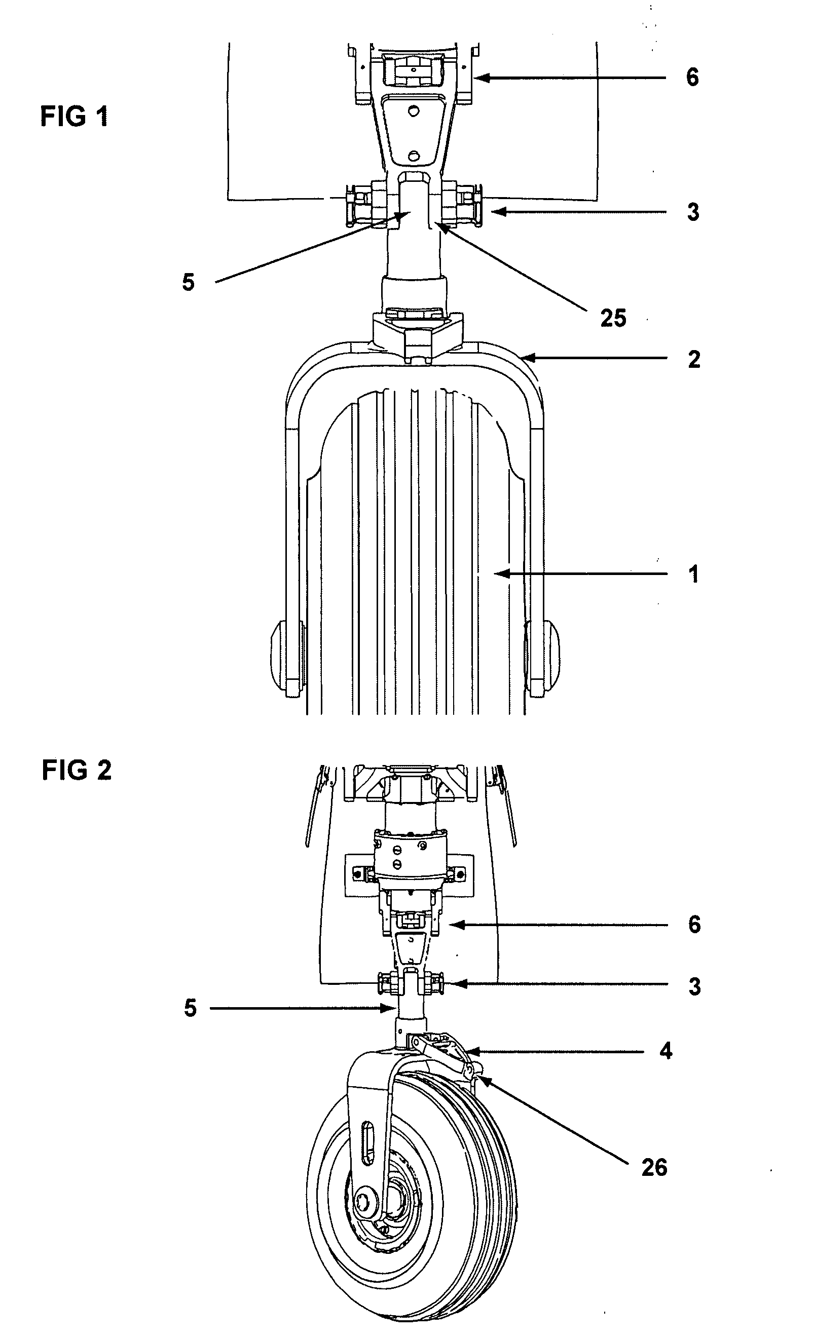
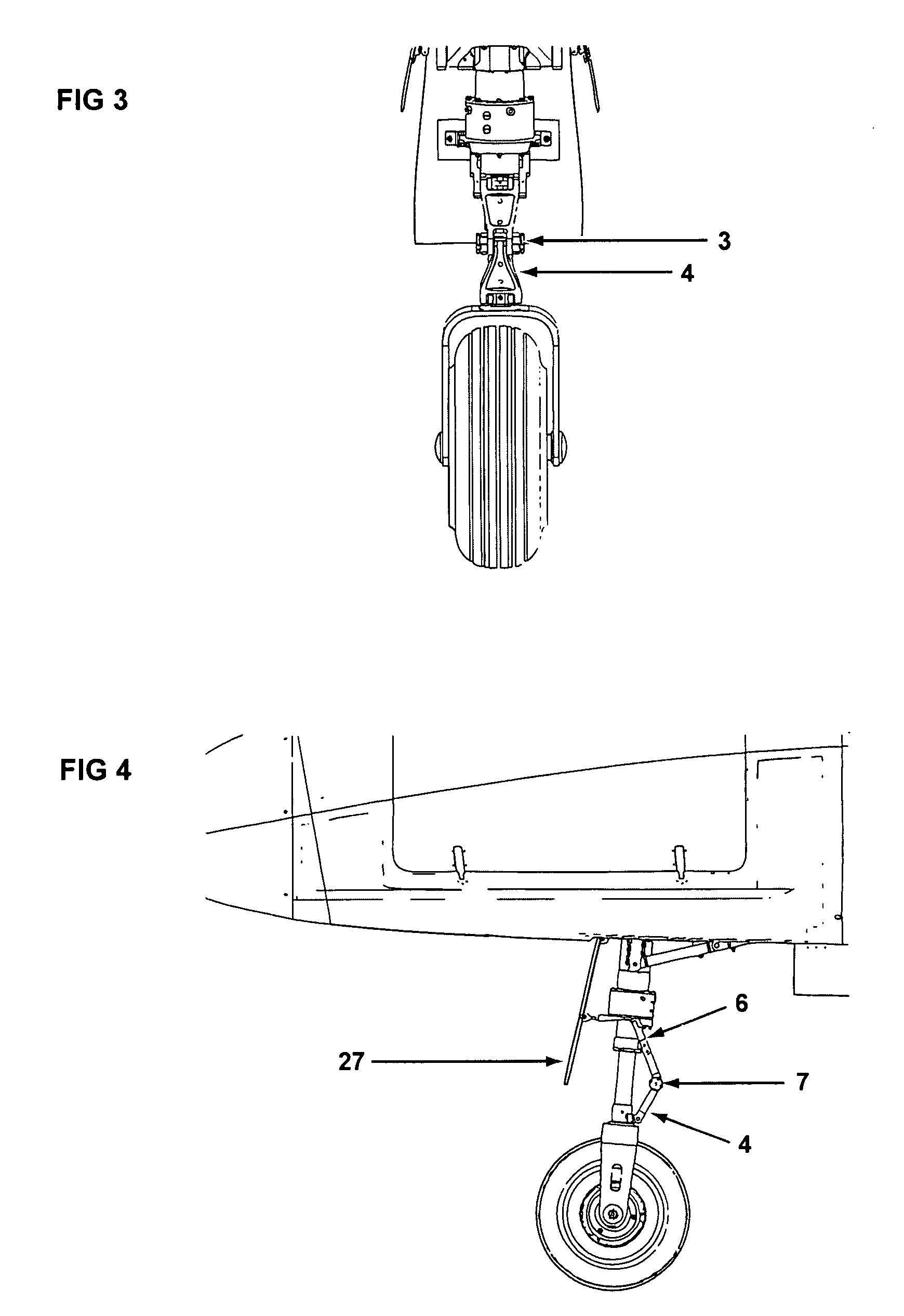
[0023]The invention includes or can be implemented with an aircraft front or nose landing gear assembly. One of ordinary skill in the art will understand the general structure, function, and capability of a nose gear assembly, and text and explanations here refer to generally known or available aspects of landing gear only to the extent necessary to understand the invention or its advantages. The landing gear assembly is comprised of a conventional shaft member connecting to a U-shaped fork 2 device to hold the tire or wheel 1. The shaft can have one or more shock and / or vibration dampening devices or elements at higher regions, above the tire end and connected through the main shaft of the landing gear. An upper shaft section of the landing gear device of the invention is generally rotationally fixed and does not rotate with steering input or with the front nose wheel 1 when turned side to side. In addition, the nose landing gear assembly comprises steering mechanisms, such as a st...


PUM


Abstract

The invention relates to an assembly for controlling the rotational degree of freedom for an aircraft landing gear wheel, which can advantageously be used to prevent damage to the aircraft during taxing. In a general embodiment, an upper connection arm is supported by the descending shaft of the landing gear and a pivoting control arm is affixed to a lower region of the landing gear, and a control lock can be used to connect the connection arm to the control arm in order to restrict the rotation of the wheel to a desired range.

Description

FIELD OF THE INVENTION[0001]The invention relates to aircraft landing gear and more particularly to a system for conveniently locking and un-locking the degree of rotation in a nose gear turning radius. In a preferred example, an easily replaceable or removable locking device for aircraft landing gear is employed, where the locking device has an engaged position preventing damage to aircraft from over-rotation and a visible locked position indicator. In addition, the locking device has a released position, which permits full or a greater degree of rotational freedom of the nose landing gear. The system can be designed so that aircraft operators or taxiway employees can visually inspect the locking device, and most preferably from inside the aircraft.BACKGROUND OF THE INVENTION[0002]In many airport settings, towing and moving of aircraft is often required by ground vehicles due to airport restrictions and space limitations. Commonly used tow tug vehicles attach to the forward landing...

Claims


Application Information

Patent Timeline
IPC IPC(8): B64C25/26
CPCB64C25/50
Inventor O'CONNELL, CHARLES
Owner ADAM AIRCRAFT INDUSTRIES
Why Eureka
Try Eureka