Micromechanical Capacitive Pressure Transducer and Production Method

a capacitive pressure transducer and micro-mechanical technology, applied in the direction of fluid pressure measurement, fluid pressure measurement by electric/magnetic elements, instruments, etc., can solve problems such as unsatisfactory leakage currents

Inactive Publication Date: 2009-04-23
ROBERT BOSCH GMBH
View PDF3 Cites 29 Cited by
  • Summary
  • Abstract
  • Description
  • Claims
  • Application Information

AI Technical Summary

Benefits of technology

[0007]The use of surface-micromechanical method steps to produce the capacitive pressure transducer makes the production much more cost-effective since only one surface requires processing. As a result, no time-consuming epitaxy steps with subsequent patterning are required that must be implemented multiple times one after the other. Capacitive sensor elements having small lateral and vertical dimensions relative to the substrate are therefore able to be produced with the aid of the provided method. Due to the micromechanical sensor structure produced in this manner, the capacitive sensor element is able to be operated at low power consumption. It is especially advantageous in this context that already known standard processes of surface micromechanics (SMM) may be utilized for the production. Using a monolithic design makes it possible to integrate the utilized micromechanics together with the microelectronics on one chip. It is especially advantageous that the two electrodes are electrically completely insulated from one another, so that no leakage currents will flow. Parasitic capacitances caused by pn transitions are omitted.
[0010]To reinforce the diaphragm, an epitaxy layer, which is covered by the first layer, may be deposited on the surface of the semiconductor substrate or on the second electrode. It is especially advantageous in this context if the first layer contains a dielectric material. Prior to applying the epitaxy layer, a topology may optionally be produced in the epitaxy layer at the edge of the cavity or diaphragm, for example using a LOCOS process or a LOCOS process with subsequent removal of the LOCOS layer. This topology may be used to adjust the sensitivity of the pressure sensor via the rigidity of the diaphragm edge.
[0011]Sacrificial-layer etching holes are advantageously formed in the first layer in the lateral region of the diaphragm. These sacrificial-layer etching holes constitute the access for separating the second electrode from the semiconductor substrate with the aid of the etching process. In one special further development of the exemplary embodiments and / or exemplary methods of the present invention, the etching process may also be used for a separation of the applied epitaxy layer. In so doing, the epitaxy layer above the cavity may be separated from the epitaxy layer above the semiconductor substrate surrounding the cavity. In this way a (local) thickening of the diaphragm by the epitaxy layer is possible.

Problems solved by technology

The sensor element described in the document has the disadvantage that the two electrodes are insulated from one another only via pn transitions, which constitute parasitic capacitances and lead to undesired leakage currents.

Method used


Image

  • Micromechanical Capacitive Pressure Transducer and Production Method
  • Micromechanical Capacitive Pressure Transducer and Production Method
  • Micromechanical Capacitive Pressure Transducer and Production Method

Examples


Embodiment Construction

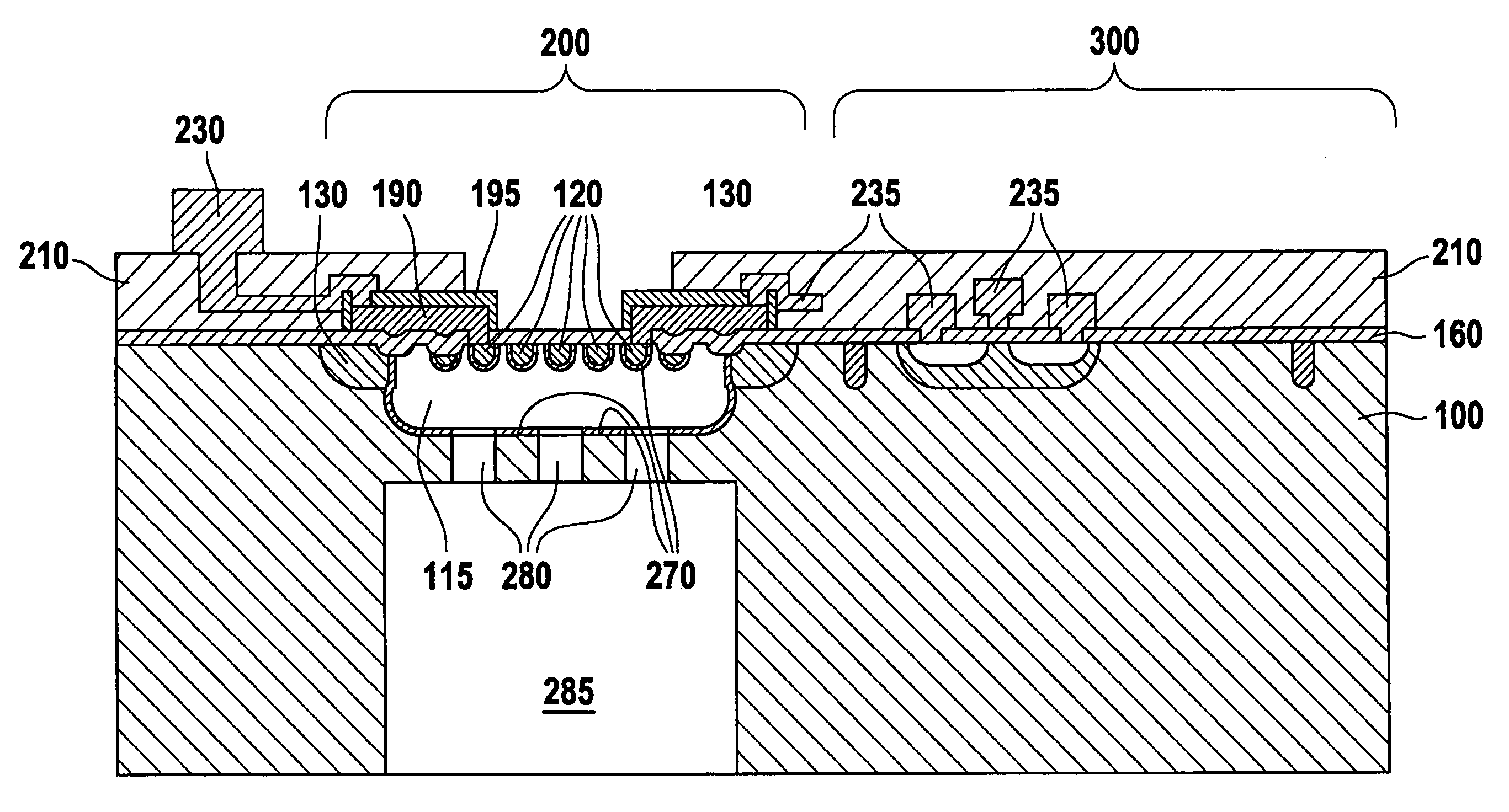
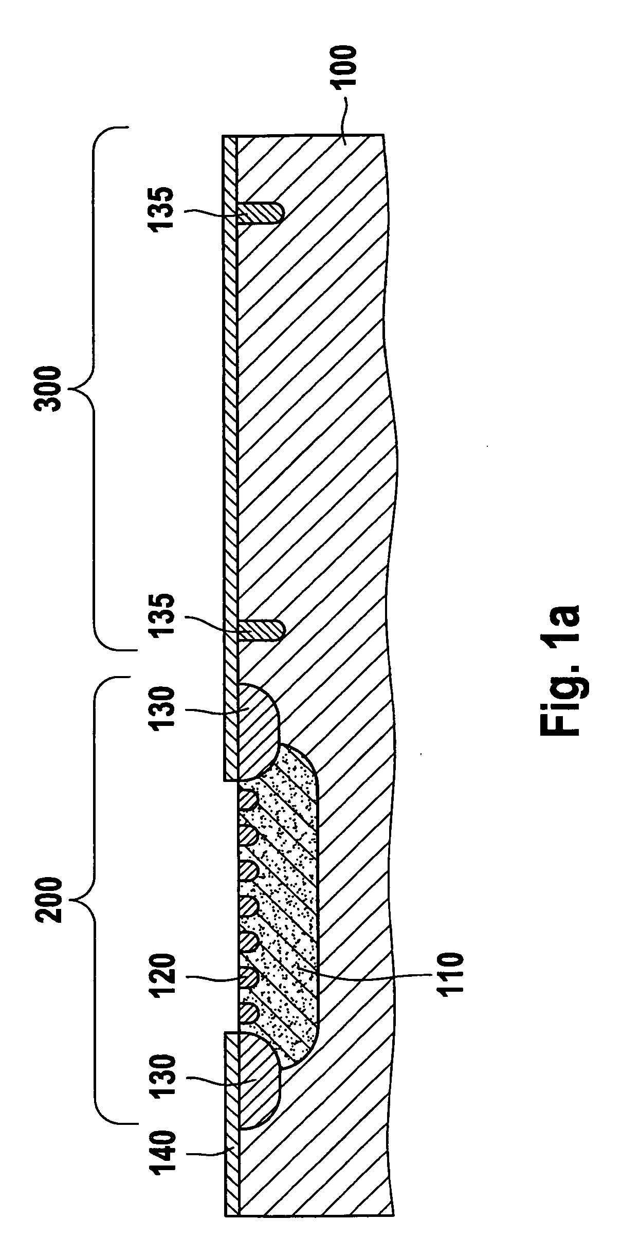
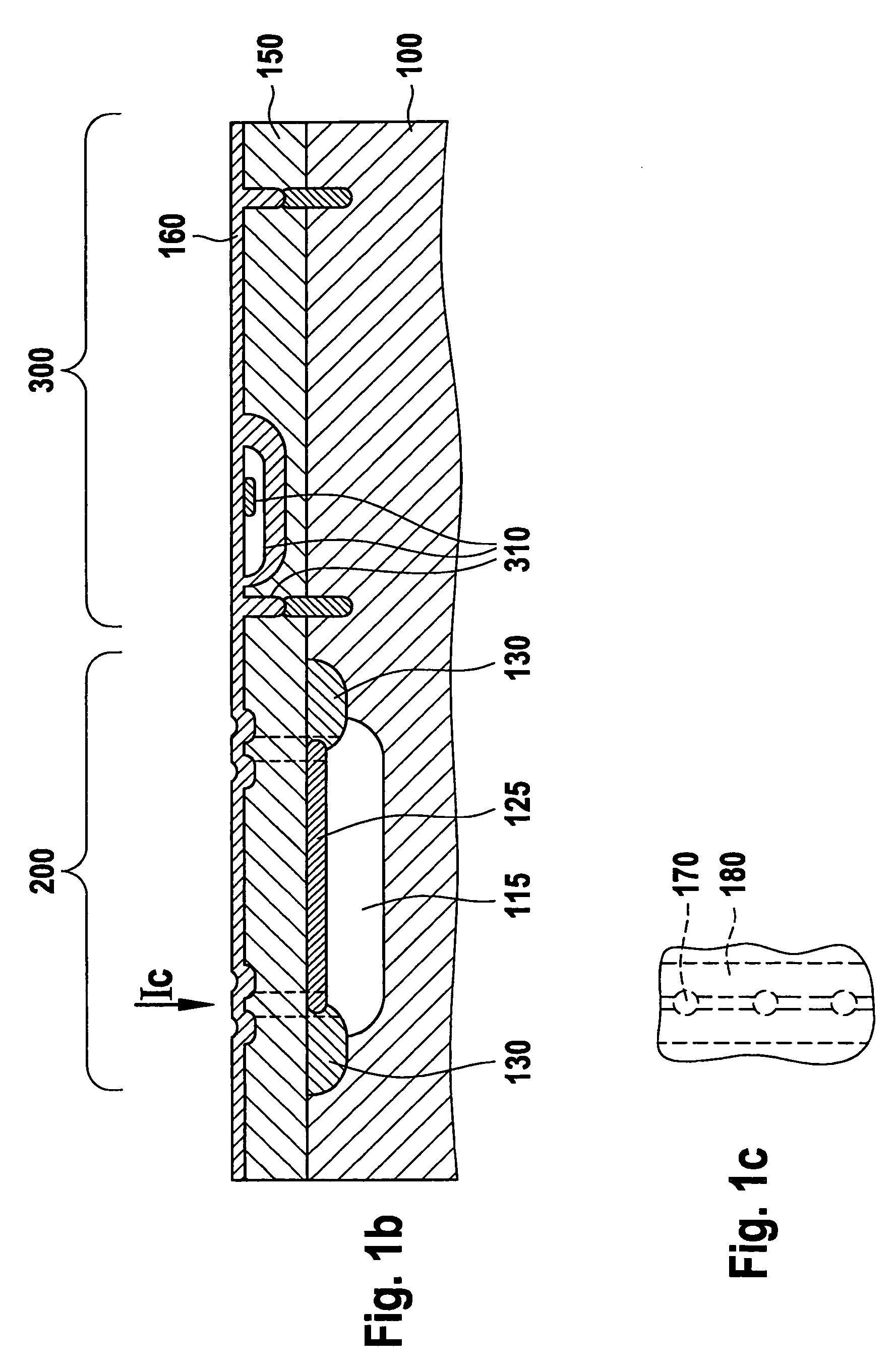
[0020]A capacitive pressure measurement requires electrodes that are set apart and electrically insulated from one another, which should be electrically controlled individually. According to the exemplary embodiments and / or exemplary methods of the present invention, these electrically insulated electrodes are worked out of a semiconductor substrate. The first electrode may be formed by the use of a doped semiconductor substrate itself. In an additional exemplary embodiment, however, it is also possible to produce the first electrode in the semiconductor substrate by doping the semiconductor substrate in a spatially restricted region.

[0021]According to the exemplary embodiments and / or exemplary methods of the present invention, the second electrode, which may likewise be made of the semiconductor material and is worked out of the semiconductor substrate and possibly the epitaxy layer, may be flexibly suspended on the substrate above a cavity by a dielectric layer. Optionally, it may...


PUM


Abstract

The present invention describes a method for producing a micromechanical capacitive pressure transducer and a micromechanical component produced by this method. First, a first electrode is produced in a doped semiconductor substrate.In a further method step, a diaphragm with a second electrode is produced at the surface of the semiconductor substrate. Furthermore, it is provided to apply a first layer, which preferably is made of dielectric material, on the diaphragm and the semiconductor substrate. With the aid of this first layer, the diaphragm and the semiconductor substrate of the finished micromechanical capacitive pressure transducer are mechanically connected to one another directly or indirectly. Furthermore, a buried cavity is produced in the semiconductor substrate between the first and second electrode. In a following etching step, the diaphragm is finally dissolved out of the semiconductor substrate through openings in the first layer, the mechanical connection from the diaphragm to the semiconductor substrate being accomplished with the aid of the first layer. Due to this mechanical connection the diaphragm or the second electrode is able to be movably suspended above the first electrode.

Description

FIELD OF THE INVENTION[0001]The present invention relates to a method for producing a micromechanical capacitive pressure transducer and to a micromechanical component produced according to this method.BACKGROUND INFORMATION[0002]A method for producing micromechanical sensors is discussed in German patent document DE 101 14 036 A1. There, openings, which transform themselves into cavities in the depth of the substrate under a sealed diaphragm cover during a subsequent heat treatment, are introduced in a semiconductor substrate. A capacitive pressure sensor can be produced by this method, the cavity being created between two doping zones in the substrate. If these two zones are electrically insulated from one another they form a plate-type capacitor whose capacitance depends on the spacing of the doping zones. Both doping zones can be electrically connected to a suitable evaluation circuit by deep contacting. A deformation of the semiconductor substrate can thus be converted into a m...

Claims


Application Information

Patent Timeline
Patent Type & Authority Applications(United States)
IPC IPC(8): H01L21/20H01L29/84
CPCG01L9/0073B81C1/00G01L9/00
Inventor LAMMEL, GERHARDBENZEL, HUBERTARMBRUSTER, SIMONSCHELLING, CHRISTOPHBRASAS, JOERG
Owner ROBERT BOSCH GMBH
Why Eureka
Try Eureka