Motor vehicle seat

a technology for motor vehicles and seat covers, applied in the field of vehicle seats, can solve the problems of inefficiency of the type of lumbar support used, achieve the effects of enhancing reliability, enhancing ergonomic and comfort characteristics, and enhancing the effect of efficiency and us

Inactive Publication Date: 2009-04-23
LEAR CORP
View PDF6 Cites 52 Cited by
  • Summary
  • Abstract
  • Description
  • Claims
  • Application Information

AI Technical Summary

Benefits of technology

[0008]In its general terms, the present invention involves a vehicle seat having an active headrest system including a lumbar support device of an uncomplicated and economical design that provides heightened ergonomic and comfort characteristics. The seat has an active headrest system distinguished by a heightened effectiveness and efficiency of use, in terms of

Problems solved by technology

For example, the type of lumbar support used is not efficient from th

Method used


Image

  • Motor vehicle seat
  • Motor vehicle seat
  • Motor vehicle seat

Examples


Embodiment Construction

)

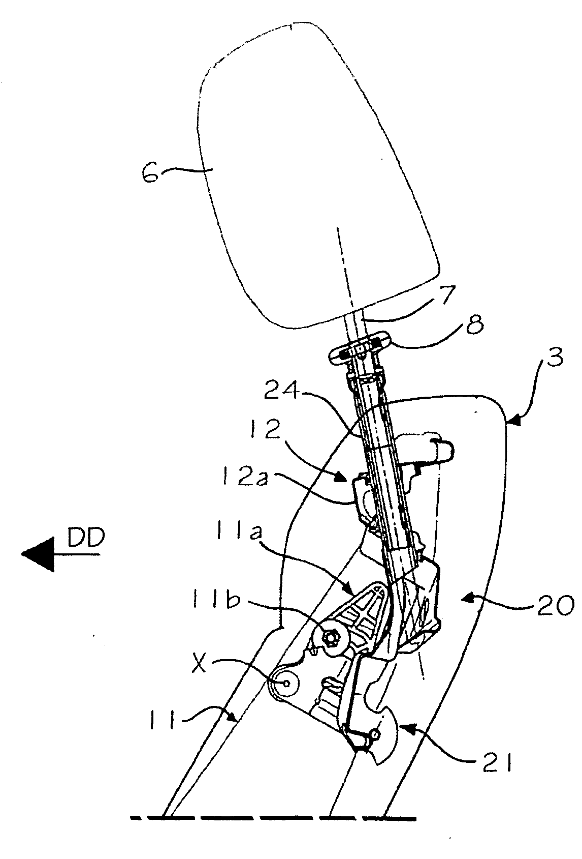
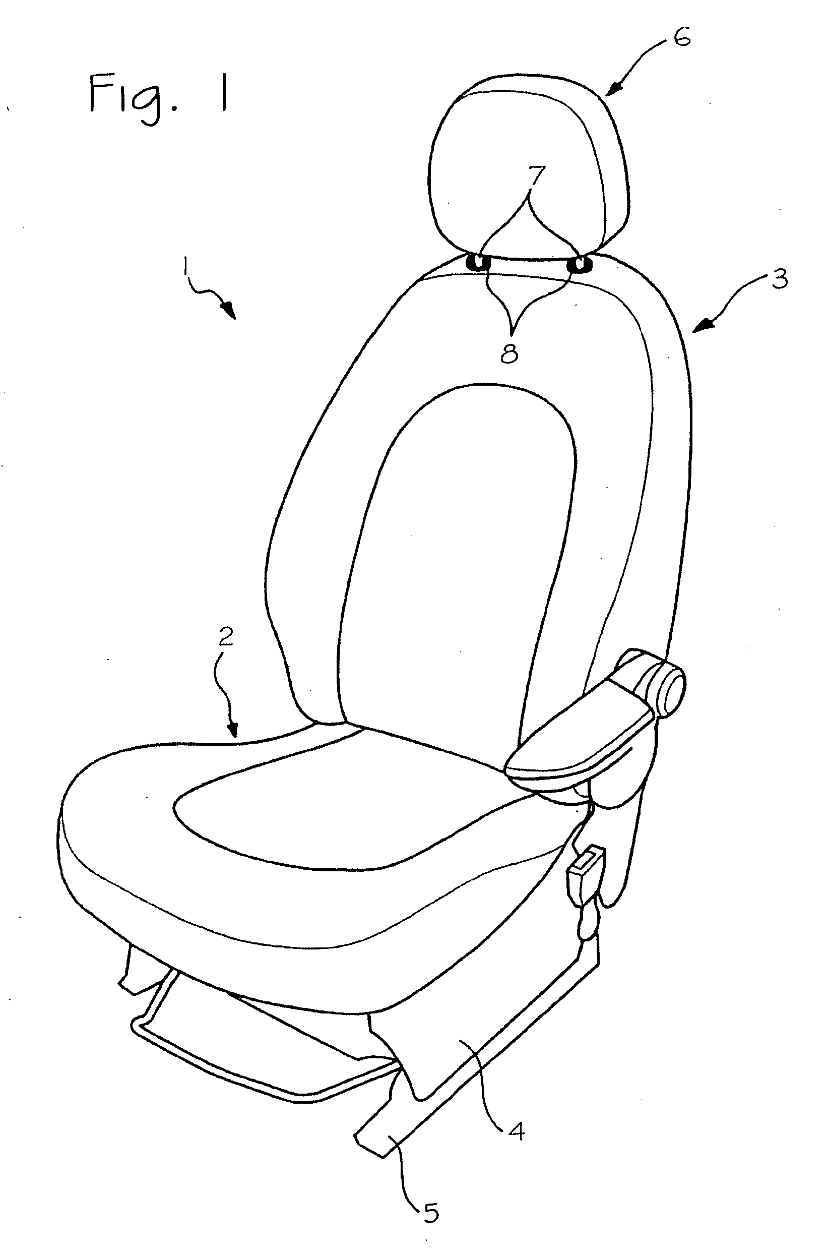
[0025]As shown in FIG. 1, a vehicle seat 1 constructed according to the present invention includes a seat cushion 2 and a seat back 3. The seat cushion 2 includes a metallic framework operatively coupled to lower slide rails 5 for securement to the floor of the passenger compartment of any type of vehicle, not shown. The lower extremity of the seat back 3 is hinged to the structure 4 of the seat cushion 2, so as to allow adjustment of its inclination. A headrest 6 is mounted on the seat back 3 by support rods 7 inserted in adjustable manner in plastic bushings 8 secured to the upper ends of respective tubular guide elements that are internal to the seat back and hereinafter described.

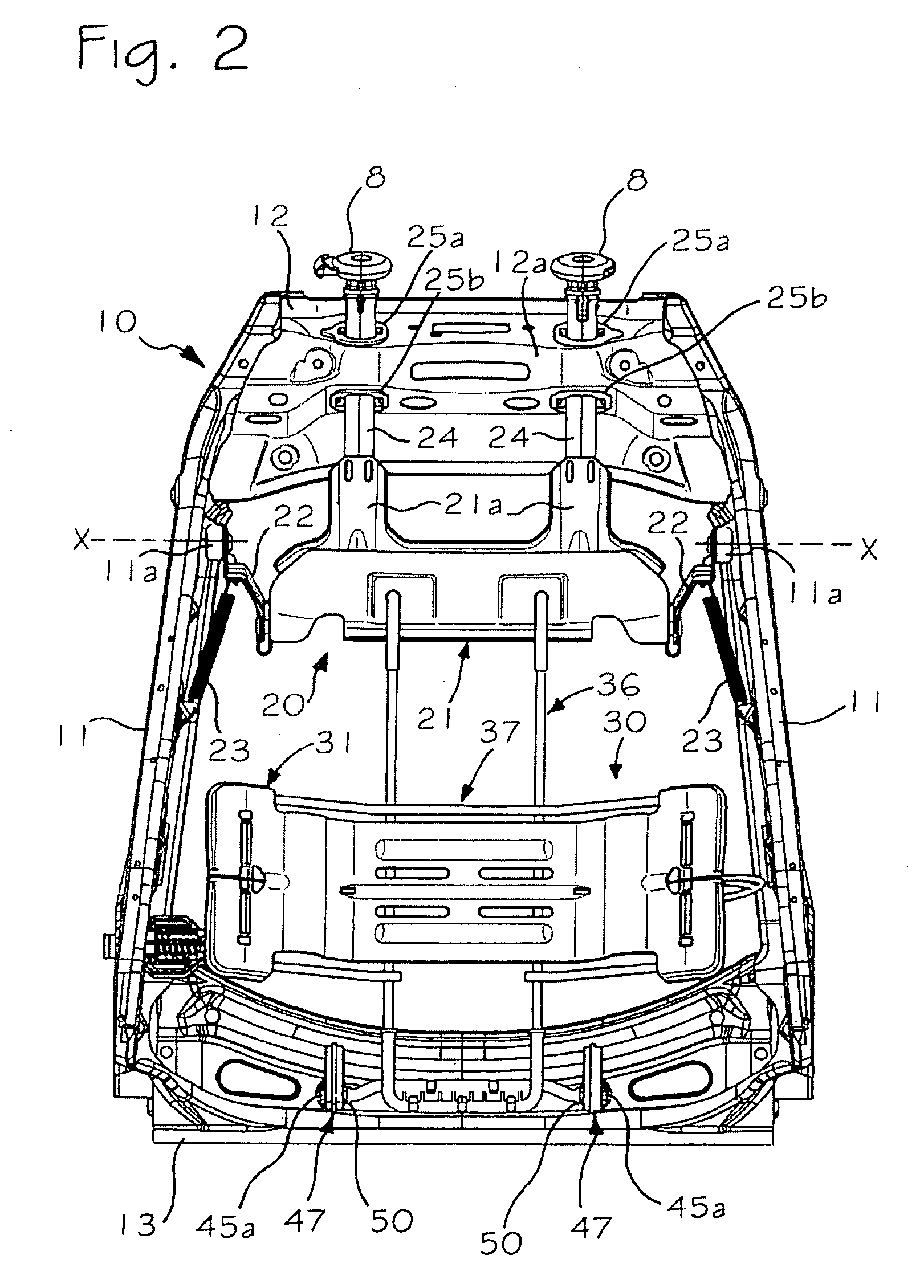
[0026]The seat back 3 disclosed includes a headrest system of active type, i.e., designed to move forwardly during an impact. In seats of this type, the internal frame of the seat back is linked in movable manner to a support mechanism of the headrest. This movable mechanism is basically located in the...


PUM


Abstract

A vehicle seat (1) having an active headrest mechanism (20) actuated by a lower lumbar mechanism (30). A seat back frame (10) mounts the active headrest mechanism (20) and the lower lumbar mechanism (30).

Description

CROSS-REFERENCE TO RELATED APPLICATIONS[0001]This application claims foreign priority benefits under 35 U.S.C. §119(a)-(d) to TO 2007A000747, filed Oct. 22, 2007, which is hereby incorporated by reference in its entirety.BACKGROUND OF THE INVENTION[0002]1. Field of the Invention[0003]The present invention relates to a vehicle seat having an active headrest system and also relates to a lumbar support device.[0004]2. Background Art[0005]U.S. Pat. No. 7,044,544 discloses a vehicle seat back having a lumbar support element utilized as an activating element for an active headrest system. A lumbar support element of vertical operation is mounted on vertical rods having upper ends coupled to an impact body of the active headrest system. The lower ends of the rods are welded to a horizontal rod having opposite ends inserted into respective parallel guides that are secured to a lower cross beam of the frame of the seat back, with each of the guides defining an upwardly facing cam surface.[00...

Claims


Application Information

Patent Timeline
IPC IPC(8): B60N2/427B60N2/48B60N2/66
CPCB60N2/66B60N2/4885B60N2/6671B60N2/888
Inventor D'AGOSTINI, ROBERTOFALCHERO, ANGELO
Owner LEAR CORP
Why Eureka
Try Eureka