Cylindrical Rapid Prototyping Combined Tool

A combined tool and fast technology, applied in the field of metal cutting, can solve the problems of difficult to guarantee product quality, lengthened axial length and high production cost, and achieve the effect of good product quality, low production cost and high work efficiency

Inactive Publication Date: 2015-12-02
ZHEJIANG GEELY POWERTRAIN CO LTD +3
View PDF6 Cites 0 Cited by
  • Summary
  • Abstract
  • Description
  • Claims
  • Application Information

AI Technical Summary

Problems solved by technology

[0003] The purpose of the present invention is to solve the problems of many procedures, low work efficiency, high production cost and difficult to guarantee the product quality existing in the processing of the outer circular surface of the irregular workpiece in the prior art, and to provide a simple process, high work efficiency and low production cost. Cylindrical Rapid Prototyping Combined Tool with Low Cost and Good Product Quality
On the other hand, since the axial length of the tool holder is significantly longer than the existing structure, it can process longer workpieces, which solves the defect that the tools in the prior art can only process shorter workpieces

Method used


Image

  • Cylindrical Rapid Prototyping Combined Tool
  • Cylindrical Rapid Prototyping Combined Tool
  • Cylindrical Rapid Prototyping Combined Tool

Examples


Embodiment 1

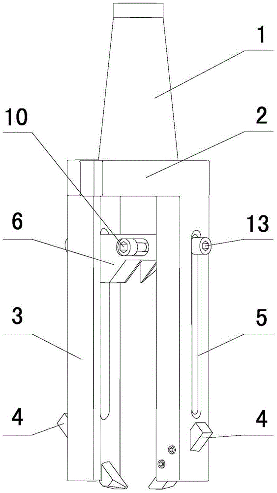
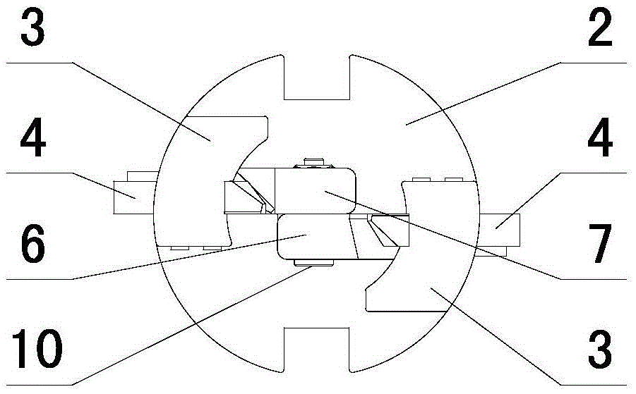
[0033] in such as figure 1 figure 2 In the shown embodiment 1, a cylindrical rapid prototyping combination tool includes a knife handle arranged on the centerline of tool rotation, the lower end of the knife handle 1 is provided with a tool rest disc 2, and the axial direction of the outer edge of the tool rest disc is A tool rack for fixing processing tools is provided on the top, and the tool rack is a pair of cutting racks 3 arranged on both sides of the tool rotation centerline. The end of the cutting rack away from the tool holder disc is provided with a cutter head pointing to the direction of the tool rotation center line. The outer circle cutting knife 4, the outer circle cutting knife is offset on the cutting frame, and the outer circle cutting knife is close to the front part of the cutting frame rotation direction. The cutting frame between the tool holder disc and the outer circular cutting knife is provided with a fixed groove 5 in the axial direction, and a cha...

Embodiment 2

[0035] The cross-section of the cutting frame in Example 2 is fan-shaped, and the cutting frames on both sides and the outer circular cutting knives arranged on the cutting frame are symmetrically arranged with the center line of the tool rotation as the axis, and the outer circular cutting knives on the cutting frames on both sides Its rake face is on the same center plane of the tool, and the outer circular cutting tool is inclined on the cutting frame. Set screw for cutter. The included angle between the outer circle cutter and the cutting frame is 45 degrees, the cross section of the handle of the outer circle cutter is rectangular, and the side of the handle of the cutter holder is provided with a sawtooth structure 14 (see Figure 10 ), there is a corresponding sawtooth structure on the joint surface of the cutting frame and the handle, the tooth tip angle of the sawtooth structure is 90 degrees, the length of the slope on both sides of the tooth tip is 0.5 mm, the head ...

Embodiment 3

[0037] A pair of rolling frames 15 (see Figure 11 ), the end of the rolling frame far away from the knife holder disc is provided with a rolling device 16 protruding toward the direction of the tool rotation centerline (see Figure 8 ), the distance between the rolling device and the tool holder is smaller than the distance between the head of the outer circular cutting knife and the tool holder. The rolling device includes a cylindrical ball fixing sleeve 17 arranged vertically with the rolling frame. The ball fixing sleeve is provided with an external thread, and the ball fixing sleeve is screwed with the rolling frame through the external thread. There is an opening, the steel ball 18, the steel bowl 19 and the compression spring 20 are arranged in sequence in the ball fixing sleeve, and one end of the compression spring is connected to the adjusting screw 21, the diameter of the opening end of the ball fixing sleeve is smaller than the diameter of the steel ball, and a pa...


PUM


Abstract

The invention discloses a cylindrical rapid-shaping combined cutter. The cylindrical rapid-shaping combined cutter comprises a cutter handle which is arranged on the rotating centerline of the cutter, wherein a cutter frame disc is arranged at one end of the cutter handle, a plurality of tool racks which are used for fixedly arranging machining tools are axially arranged at the outer edge of the cutter frame disc, each tool rack comprises a pair of cutting frames which are arranged at the two sides of the rotating centerline of the cutter, excircle cutting knives, of which knife heads are pointed to the direction of the rotating centerline of the cutter, are arranged at one ends, far away from the cutter frame disc, of the cutting frames, fixing grooves are axially formed in the cutting frames between the cutter frame disc and the excircle cutting knives, and chamfer cutters are arranged between the fixing grooves of the cutting frames at two sides. According to the cylindrical rapid-shaping combined cutter, the problems in the prior art that when an excircle surface of an irregular workpiece is machined, the working procedures are many, the work efficiency is low, the production cost is high and the product quality is difficult to guarantee are effectively solved, and the substantial effects of simple process, high work efficiency, low production cost and good product quality are achieved when the excircle surface of the irregular workpiece is machined by adopting the cylindrical rapid-shaping combined cutter.

Description

technical field [0001] The invention relates to the technical field of metal cutting, in particular to a cylindrical rapid prototyping combined tool for cutting the outer circular surface of irregular workpieces. Background technique [0002] With the continuous progress and development of the industry and the precision design, the parts of the equipment are now complicated and diversified. The structure of many parts is irregular, and it is impossible to use the lathe to process the outer circle of them, so give Processing poses difficulties. At present, the main method of processing the cylindrical surface of irregular workpieces is to use different types of tools to complete the processing through machining centers or boring and milling machines. The problems existing in the prior art are: 1. Too many cutting tools are used, which directly increases the amount of tool changing action for equipment operation, reduces processing efficiency, and wastes resources. The manage...

Claims


Application Information

Patent Timeline
Patent Type & Authority Patents(China)
IPC IPC(8): B23P23/00
CPCB23P23/00
Inventor 黄财明李伟飞王鹏曾苗苗孙艳陈杰王瑞平
Owner ZHEJIANG GEELY POWERTRAIN CO LTD
Why Eureka
Try Eureka