Lighting control system for a lighting device

a control system and lighting device technology, applied in the field of lighting control, can solve the problems of lack of uniformity in the manufacture of leds, less than the desired performance of lighting devices, and inability to achieve uniform light outpu

Active Publication Date: 2009-04-23
AMERICAN STERILIZER CO
View PDF33 Cites 62 Cited by
  • Summary
  • Abstract
  • Description
  • Claims
  • Application Information

AI Technical Summary

Benefits of technology

[0005]An advantage of the present invention is the provision of a lighting control system that compensates for the effects of temperature changes on the forward voltages of LEDs within a lighting device.
[0006]Another advantage of the present invention is the provision of a lighting control system that compensates for voltage variations among individual LED lighting modules to provide substantially uniform light output.
[0007]These and other advantages will become apparent from the following description taken together with the accompanying drawings and the appended claims.

Problems solved by technology

Many drawbacks have been identified in existing lighting control systems that can result in less than desired performance of a lighting device.
These drawbacks include, but are not limited to, voltage variations among LED lighting modules that result in non-uniform light output.
These voltage variations may result from the lack of uniformity in the manufacture of the LEDs used in a lighting device.
Another drawback of existing lighting control systems is the inability of the lighting circuitry to compensate for the effects of temperature changes on the LED forward voltages, such as changes required in the drive voltage caused by an increase in temperature.
In this regard, existing lighting control systems do not compensate for inherent forward voltage changes as seen by an output driver over the entire operating temperature range of the lighting device.
The foregoing drawbacks are particularly disadvantageous where the lighting device is a surgical lighthead that requires constant light output or lux readings.

Method used


Image

  • Lighting control system for a lighting device
  • Lighting control system for a lighting device
  • Lighting control system for a lighting device

Examples


Embodiment Construction

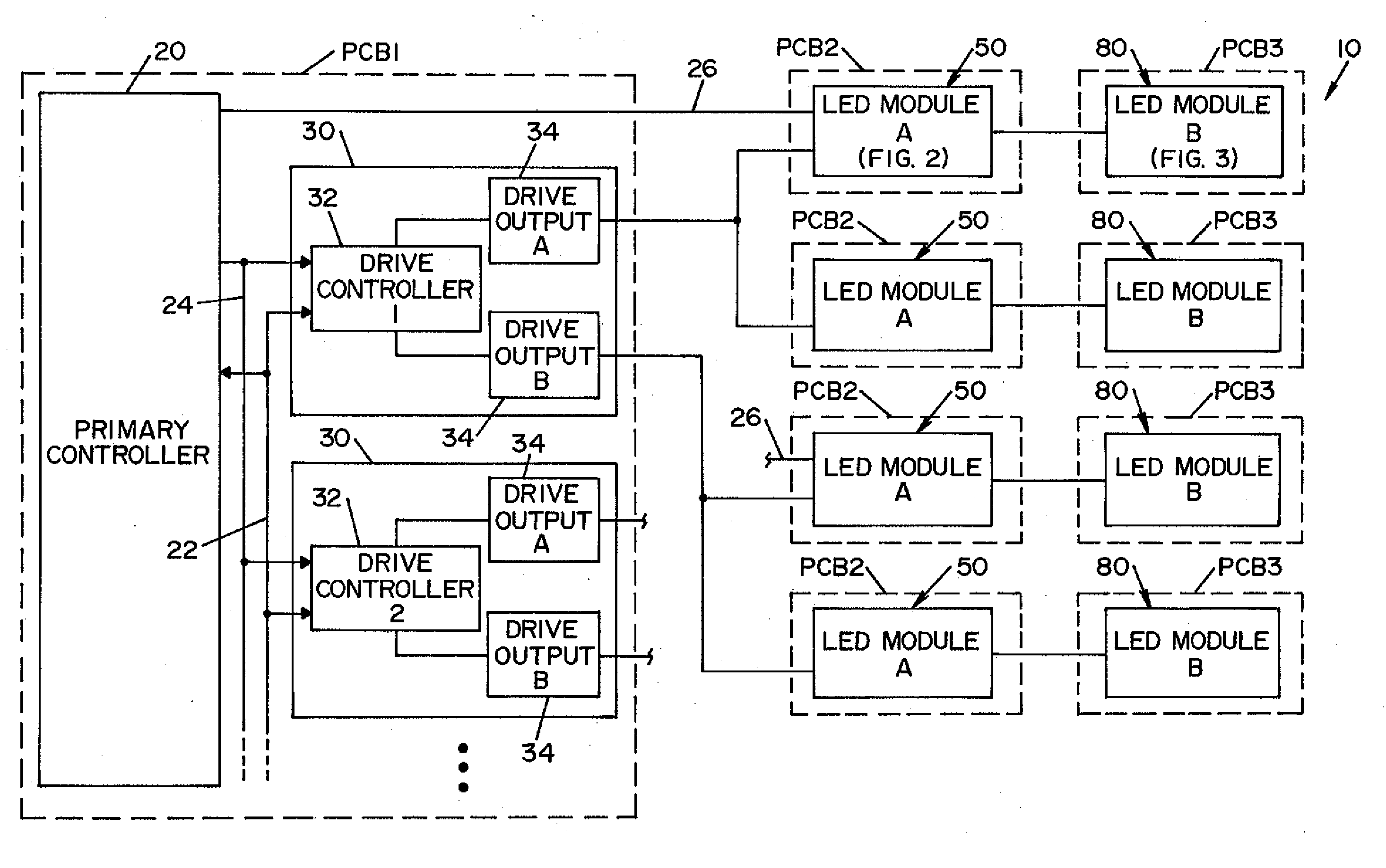
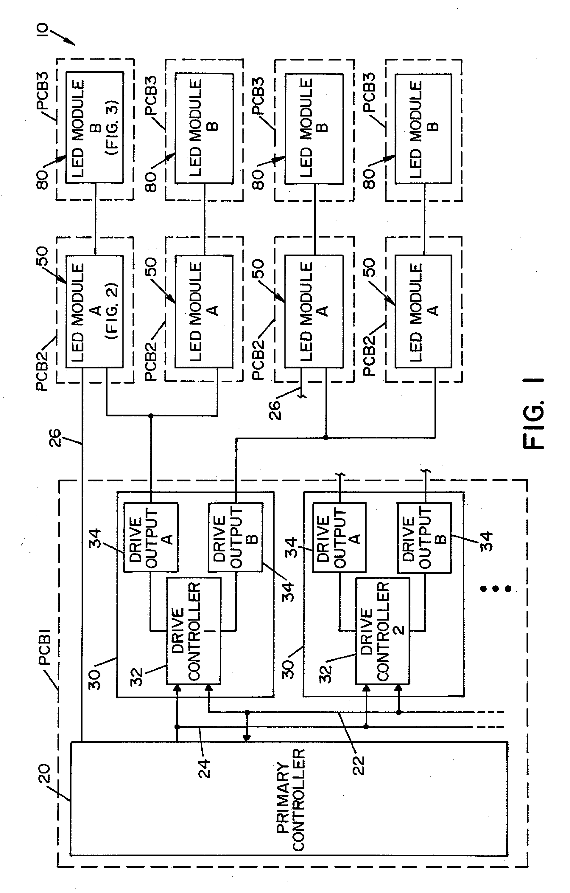
[0013]Referring now to the drawings wherein the showings are for the purposes of illustrating an embodiment of the invention only and not for the purposes of limiting same, FIG. 1 shows a block diagram of lighting control system 10 for a lighting device, such as a surgical lighthead, in accordance with an embodiment of the present invention. Lighting control system 10 is generally comprised of a primary controller 20, drive circuitry 30 comprised of at least one drive controller 32 and at least one drive output 34, one or more first LED modules 50 (module A), and one or more second LED modules 80 (module B). In the illustrated embodiment, primary controller 20 and drive circuitry 30 are located on a first printed circuit board PCB1. Each of the first and second LED modules 50 and 80 are respectively located on second and third printed circuit boards PCB2 and PCB3. Printed circuit boards PCB1, PCB2 and PCB3 may be located together within a housing (not shown) for the lighting device....


PUM


Abstract

A lighting control system suitable for a surgical lighting device. The lighting control system includes circuitry that compensates for the effects of temperature changes in a lighting device, and that compensates for forward voltage variations among LED lighting modules to provide substantially uniform light output.

Description

FIELD OF THE INVENTION[0001]The present invention relates generally to lighting control, and more particularly to a lighting control system suitable for a surgical lighting device.BACKGROUND OF THE INVENTION[0002]Many drawbacks have been identified in existing lighting control systems that can result in less than desired performance of a lighting device. These drawbacks include, but are not limited to, voltage variations among LED lighting modules that result in non-uniform light output. These voltage variations may result from the lack of uniformity in the manufacture of the LEDs used in a lighting device. Another drawback of existing lighting control systems is the inability of the lighting circuitry to compensate for the effects of temperature changes on the LED forward voltages, such as changes required in the drive voltage caused by an increase in temperature. In this regard, existing lighting control systems do not compensate for inherent forward voltage changes as seen by an ...

Claims


Application Information

Patent Timeline
Patent Type & Authority Applications(United States)
IPC IPC(8): H05B41/36H05B44/00
CPCH05B33/08H05B33/0887H05B33/083H05B45/58H05B47/235H05B45/28H05B45/00H05B45/56H05B45/48
Inventor PETRUCCI, JAMES A.DRABINSKI, TERRY A.HITE, DAVID A.RICE, SHEARI A.
Owner AMERICAN STERILIZER CO
Why Eureka
Try Eureka