Surge suppression device having one or more rings

a technology of a suppression device and a ring, applied in the direction of overvoltage protection resistors, emergency protective arrangements for limiting excess voltage/current, and arrangements responsive to excess voltage, etc., can solve the problems of affecting the operation range, affecting the repair and replacement of communications equipment, and severely damage and/or destroy communications equipmen

Inactive Publication Date: 2009-04-23
INFINITE ELECTRONICS INT INC
View PDF85 Cites 31 Cited by
  • Summary
  • Abstract
  • Description
  • Claims
  • Application Information

AI Technical Summary

Problems solved by technology

Surge variations in power and transmission line voltages, as well as noise, can change the frequency range of operation and can severely damage and / or destroy the communications equipment.
Moreover, communications equipment can be very expensive to repair and replace.
There are many sources that can cause harmful electrical surges.
The power and transmission lines act as large antennas that may extend over several miles, thereby collecting a significant amount of rf noise power from such sources as radio broadcast antennas.
Another harmful source is conductive noise, which is generated by communications equipment connected to the power and transmission lines and which is conducted along the power lines to the communications equipment to be protected.
Still another source of harmful electrical surges is lightning.
In order to achieve a consistent frequency range of operation, a low insertion loss, and a low voltage standing wave ratio (VSWR), the electrical components of these rf surge suppressors need to be manually tuned, which is imprecise and takes human labor to perform.

Method used


Image

  • Surge suppression device having one or more rings
  • Surge suppression device having one or more rings
  • Surge suppression device having one or more rings

Examples


Embodiment Construction

[0018]Apparatus, systems and methods that implement the embodiments of the various features of the invention will now be described with reference to the drawings. The drawings and the associated descriptions are provided to illustrate some embodiments of the invention and not to limit the scope of the invention. Throughout the drawings, reference numbers are re-used to indicate correspondence between referenced elements. In addition, the first digit of each reference number indicates the figure in which the element first appears.

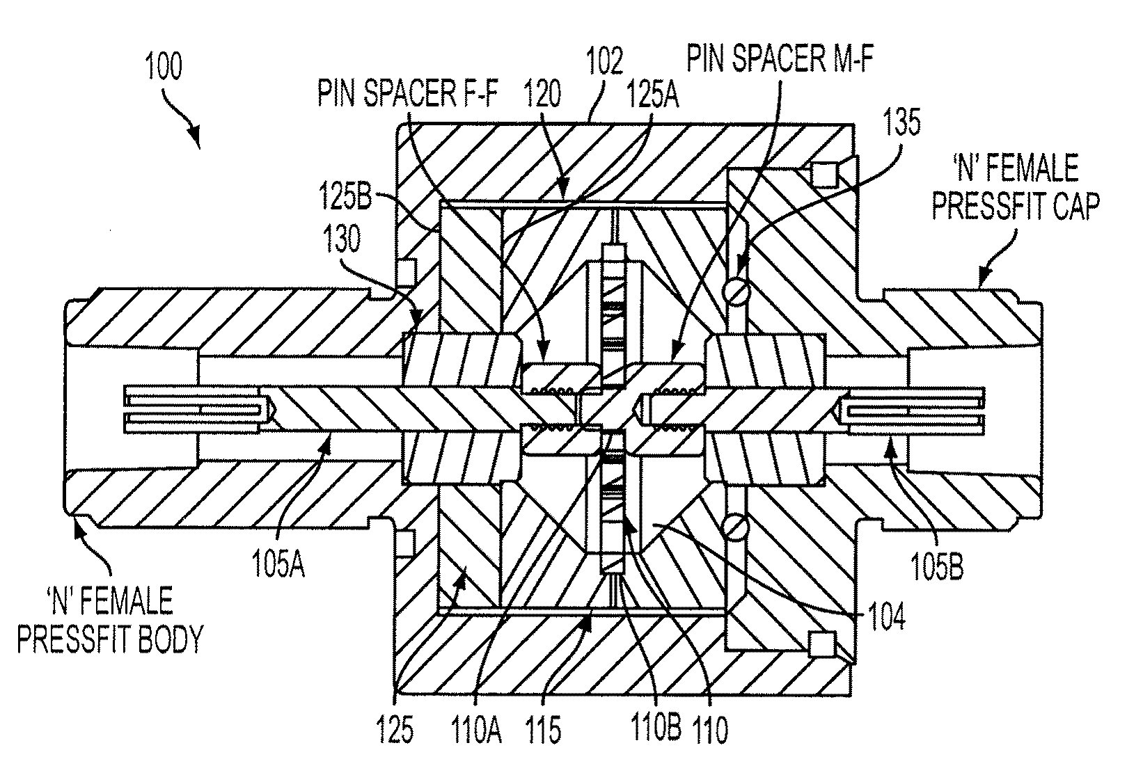
[0019]FIG. 1 is a cross-sectional view of a surge suppression device 100 according to an embodiment of the invention. The surge suppression device 100 may include a housing 102 having a cavity 104, a center conductor 105A, 105B, a spiral inductor 110, a coil capture device 115, an insulating material 120 (e.g., a Teflon tape), a ring assembly 125, a dielectric material 130 (e.g., PTFE), and an insulating spacer 135 (e.g., O-ring). The center conductor 105A, ...


PUM


Abstract

A surge suppression device may include a housing having a cavity, a center conductor positioned within the cavity, a spiral inductor having an inner curve coupled to the center conductor and an outer curve, a coil capture device connected to the outer curve of the spiral inductor, and a ring assembly having a first ring connected to the coil capture device, a second ring connected to the housing, and a voltage limiting device positioned between the first ring and the second ring.

Description

CROSS-REFERENCE TO RELATED APPLICATIONS[0001]The present application for patent claims priority from and the benefit of provisional application Ser. No. 60 / 981,028 entitled “SURGE SUPPRESSION DEVICE HAVING ONE OR MORE RINGS,” filed on Oct. 18, 2007, which is expressly incorporated by reference herein.BACKGROUND[0002]1. Field[0003]The invention relates to surge suppression. More particularly, the invention relates to a surge suppression device having one or more rings.[0004]2. Related Art[0005]Communications equipment, such as cell towers, base stations, and mobile devices, are increasingly manufactured using small electronic components which are very vulnerable to damage from electrical surges. Surge variations in power and transmission line voltages, as well as noise, can change the frequency range of operation and can severely damage and / or destroy the communications equipment. Moreover, communications equipment can be very expensive to repair and replace.[0006]There are many sour...

Claims


Application Information

Patent Timeline
Patent Type & Authority Applications(United States)
IPC IPC(8): H02H9/04
CPCH01T4/08
Inventor PENWELL, CHRISJONES, JONATHAN L.KLOBASSA, BOGDAN B.
Owner INFINITE ELECTRONICS INT INC
Why Eureka
Try Eureka