Vehicular headlamp unit

a headlamp unit and projector technology, applied in fixed installation, lighting and heating equipment, lighting support devices, etc., can solve the problem that the difference between the cut-off line of the first light distribution pattern and the cut-off line of the second light distribution pattern cannot be adequately erased

Inactive Publication Date: 2009-04-23
KOITO MFG CO LTD
View PDF13 Cites 24 Cited by
  • Summary
  • Abstract
  • Description
  • Claims
  • Application Information

AI Technical Summary

Benefits of technology

[0036]According to the above configuration, the third reflector includes a reflective surface having a focal point that is a point in a vicinity of the second light-emitting element, and a vertical cross-sectional shape formed by a parabola whose axis is an axis line that extends generally parallel to the optical axis. In such case, the third light distribution pattern with a comparatively narrow vertical width can be formed by reflected light from the third reflector, whereby a darkened portion along the cut-off lines can be efficiently eliminated.
[0037]According to the above configuration, the third reflector includes a reflective surface having a vertical cross-sectional shape formed by an ellipse whose first focal point is a point in a vicinity of the second light-emitting element and whose second focal point is a predetermined point between the second light-emitting element and the projection lens. Moreover, arranged in a downward vicinity of the projection lens is an additional projection lens having an additional optical axis that extends generally parallel to the optical axis and also having a rear-side focal point that is a point in a vicinity of the second focal point. In such case, the third light distribution pattern with a comparatively narrow vertical width can be formed by reflected light from the third reflector radiated forward via the additional projection lens, whereby a darkened portion along the cut-off lines can be efficiently eliminated.

Problems solved by technology

However, a difference in contrast above and below the cut-off line of the first light distribution pattern cannot be adequately erased, even when the second light distribution pattern is superimposed.

Method used


Image

  • Vehicular headlamp unit
  • Vehicular headlamp unit
  • Vehicular headlamp unit

Examples


Embodiment Construction

[0045]Hereinafter, embodiments of the present invention will be described with reference to the attached drawings.

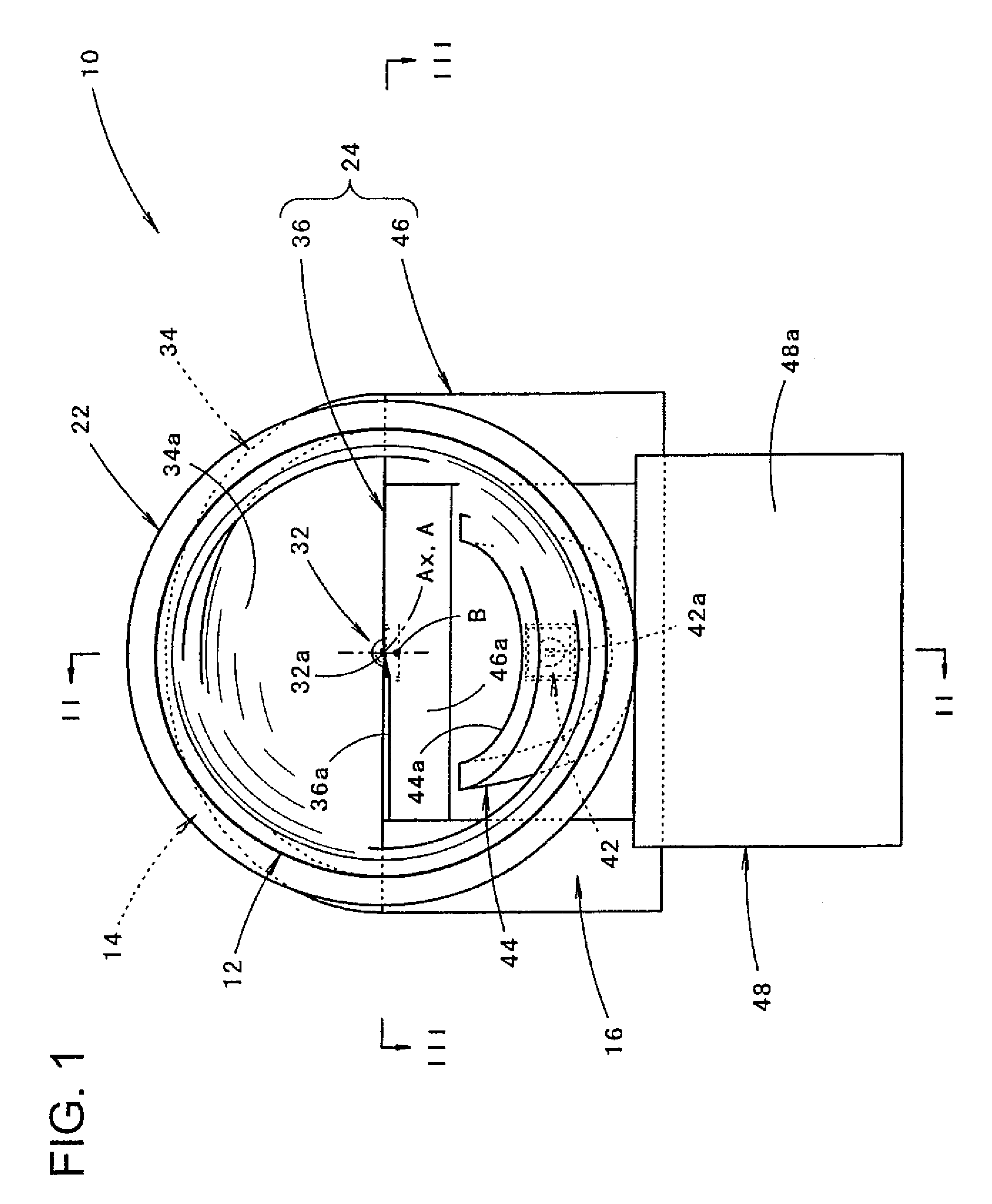
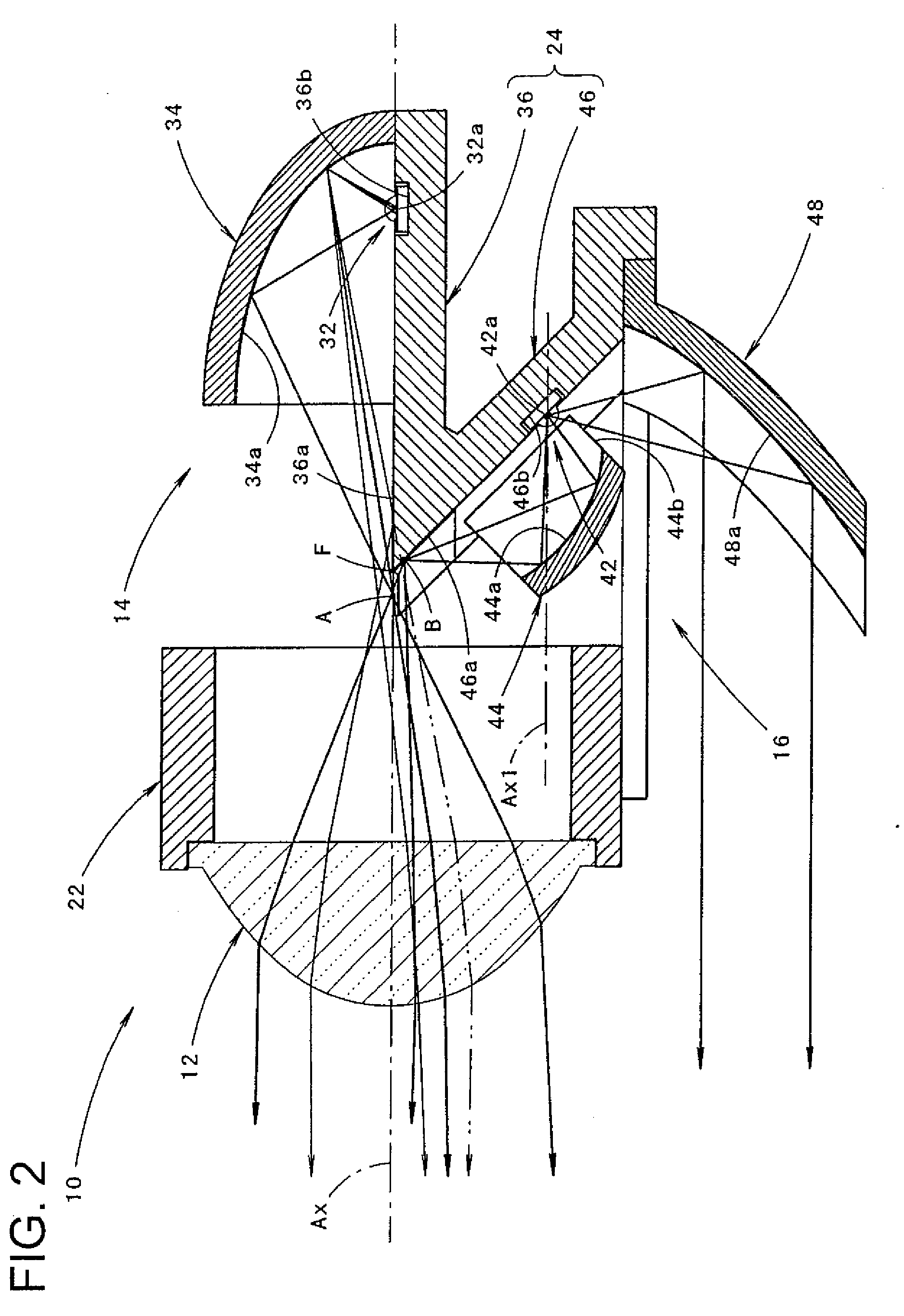
[0046]FIG. 1 is a frontal view showing a vehicular headlamp unit 10 according to an embodiment of the present invention. FIG. 2 is a cross-sectional view taken along a line II-II in FIG. 1, and FIG. 3 is a cross-sectional view taken along a line III-III in FIG. 1.

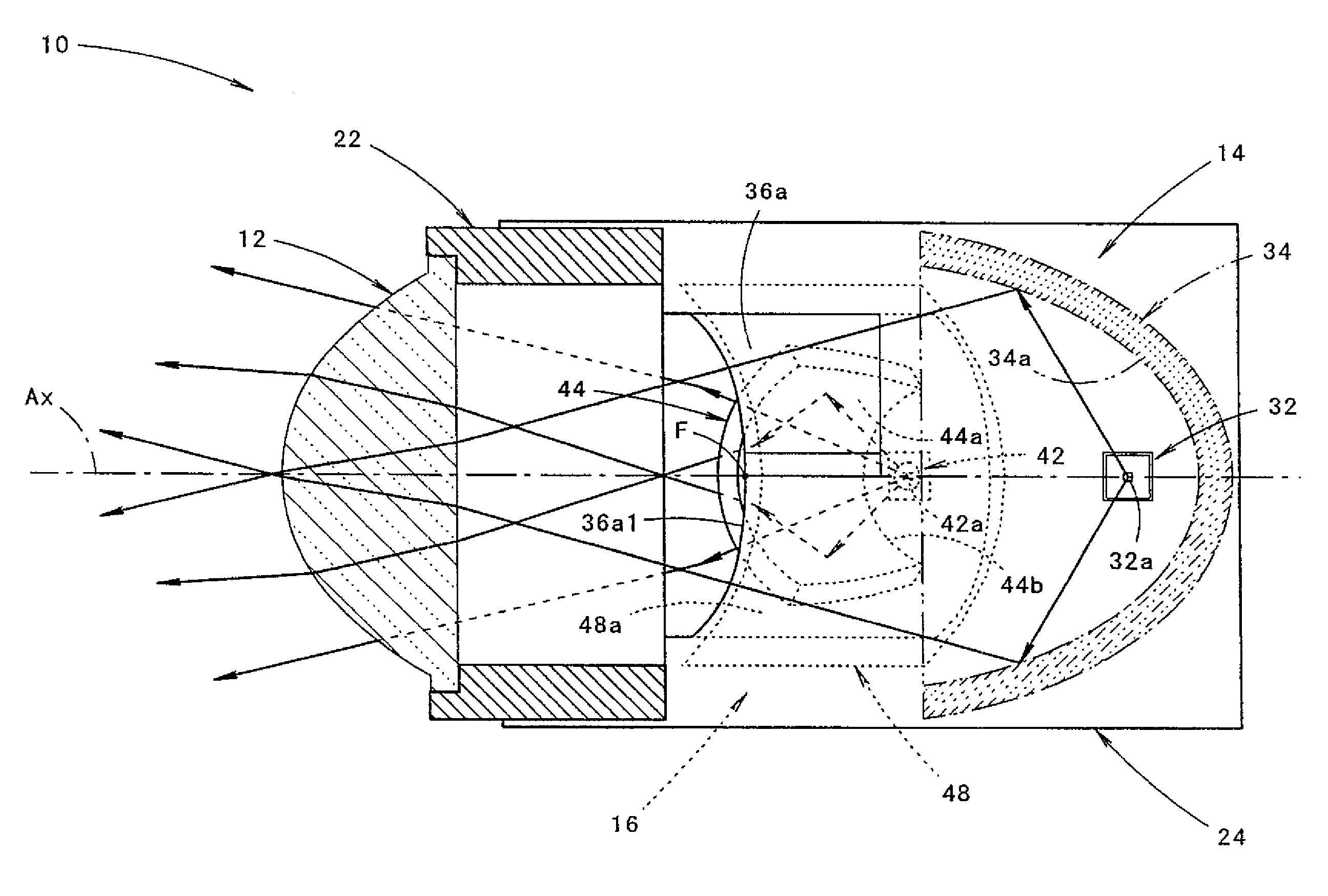
[0047]As illustrated in these figures, the vehicular headlamp unit 10 is provided with a projection lens 12 arranged on an optical axis Ax that extends in a vehicle longitudinal direction, and first and second light source units 14, 16 arranged rearward of the projection lens 12.

[0048]The vehicular headlamp unit 10 is a vehicular headlamp unit used incorporated as a portion of a headlamp. In such an incorporated state with a headlamp, the vehicular headlamp unit 10 is arranged such that the optical axis Ax extends approximately 0.5 to 0.6 degrees downward with respect to the vehicle longitudinal direction.

[0049]...


PUM


Abstract

A vehicular headlamp unit using a light-emitting element as a light source includes a projection lens arranged on an optical axis that extends in a vehicle longitudinal direction, and first and second light source units arranged rearward of the projection lens. The first light source unit includes a first light-emitting element arranged in a vicinity of the optical axis further rearward than a rear-side focal point of the projection lens, a first reflector arranged so as to cover the first light-emitting element from above and structured so as to reflect light from the first light-emitting element forward toward the optical axis, and a first mirror component having an upward-facing reflective surface that extends rearward generally along the optical axis from a vicinity of the rear-side focal point so as to reflect a portion of the reflected light from the first reflector upward. The second light source unit includes a second mirror component including a downward-facing reflective surface that extends diagonally downward toward a lamp rear side from a front end edge of the upward-facing reflective surface, a second light-emitting element arranged on the second mirror component facing forward and diagonally downward below the optical axis, a second reflector structured so as to reflect light from the second light-emitting element upward and generally converge such light at a region in a vicinity of the rear-side focal point on the downward-facing reflective surface, and a third reflector arranged downward of the second light-emitting element which reflects light from the second light-emitting element forward so that such light passes through a lower space of the projection lens.

Description

BACKGROUND OF INVENTION[0001]1. Field of the Invention[0002]The present invention relates to a projector type vehicular headlamp unit that uses a light-emitting element such as a light-emitting diode as a light source.[0003]2. Related Art[0004]A number of projector type vehicular headlamp units that use a light-emitting element such as a light-emitting diode as a light source have been proposed in recent years.[0005]Patent Documents 1 and 2 describe configurations in which such a vehicular headlamp unit is provided with a projection lens arranged on an optical axis that extends in a vehicle longitudinal direction, and first and second light source units arranged rearward of the projection lens.[0006]In the vehicular headlamp unit described in these Patent Documents, the first light source unit includes a first light-emitting element, a first reflector, and a first mirror component. The first light-emitting element is arranged in a vicinity of the optical axis further rearward than a...

Claims


Application Information

Patent Timeline
Patent Type & Authority Applications(United States)
IPC IPC(8): B60Q1/04
CPCF21Y2101/02F21S48/1159Y10S362/80F21Y2115/10F21S41/147F21S41/148F21S41/365F21S41/36F21S41/40
Inventor ISHIDA, HIROYUKI
Owner KOITO MFG CO LTD
Why Eureka
Try Eureka