Electrode for lithium ion secondary battery

Active Publication Date: 2009-04-23
PANASONIC CORP
View PDF8 Cites 10 Cited by
  • Summary
  • Abstract
  • Description
  • Claims
  • Application Information

AI Technical Summary

Benefits of technology

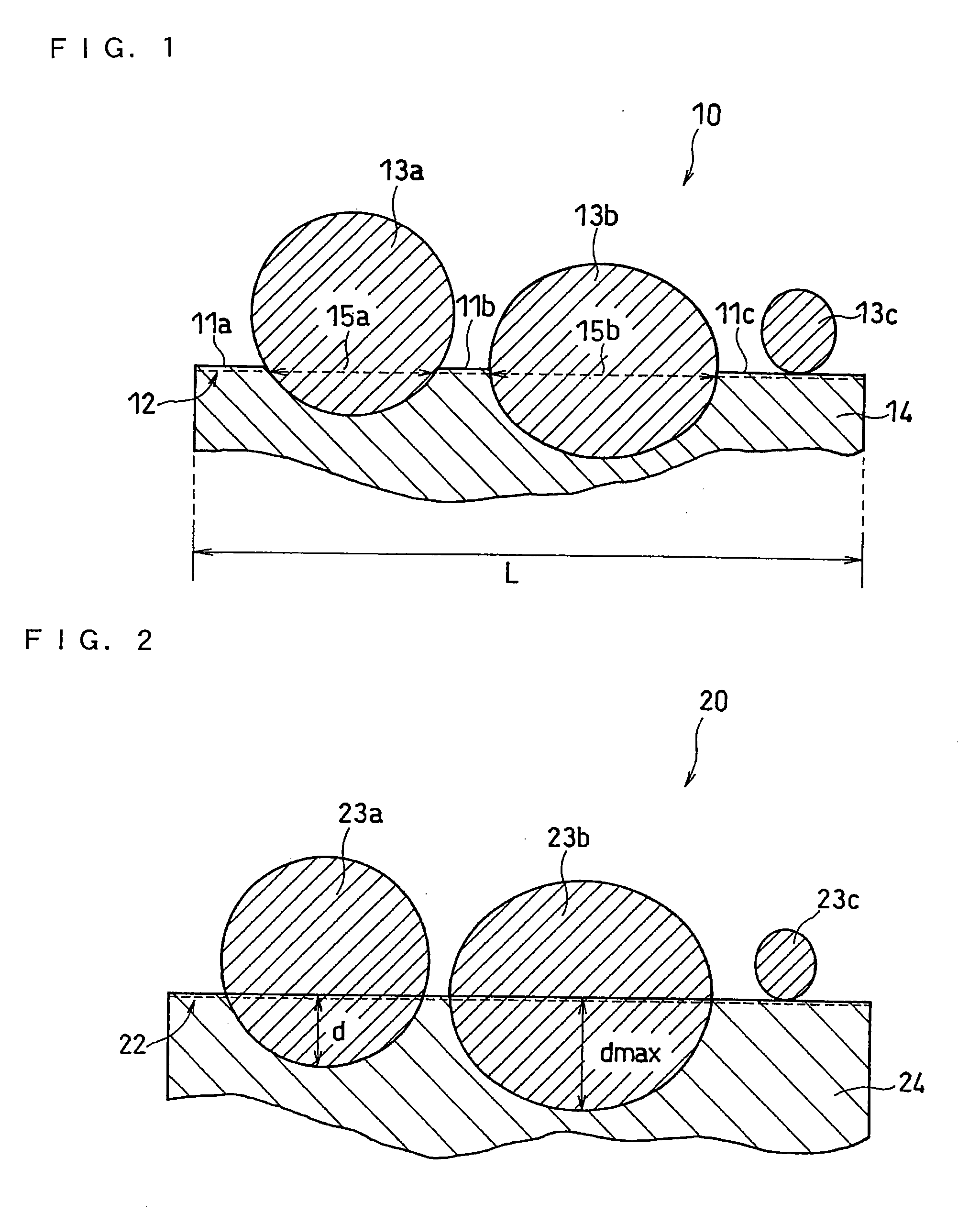
[0015]Because a plurality of recessed portions are present on the surface of a current collector, the adhesion between the material mixture and the current collector is improved. Accordingly, even under such severe conditions (e.g., a nail penetration test) as to cause damage on electrode plates, the exposure of the current collector is suppressed to the minimum. Thus, i

Problems solved by technology

Accordingly, a further improvement in safety has been an important issue for lithium ion secondary batteries.
In the tests, if a material mixture is detached from a current collector, forming an exposed portion of the highly conductive current collector, a possibility increases that a large current may flow or excessive heat generation may occur.
Conventionally, attempts have been made to insure safety by using an electric circuit including a fu

Method used


Image

  • Electrode for lithium ion secondary battery
  • Electrode for lithium ion secondary battery
  • Electrode for lithium ion secondary battery

Examples


example 1

(i) Production of Positive Electrode

[0043]As a positive electrode active material, LiCoO2, that is, a lithium-containing composite oxide represented by formula (1): LixCo1-y-zNiyMzO2 where y=z=0, having an average particle size of 7.5 μm was used.

[0044]The positive electrode active material was mixed with acetylene black serving as a conductive material and polytetrafluoroethylene (PTFE) serving as a binder at a weight ratio of 90:5:5, to which an appropriate amount of an aqueous solution of 1 wt % carboxymethyl cellulose (CMC) was added so as to obtain a positive electrode material mixture slurry.

[0045]The positive electrode material mixture slurry was applied onto both surfaces of a 15 Nm thick aluminum foil serving as a current collector, followed by drying at 110° C. The current collector was then heated at 275° C. for 6 hours to soften the current collector. Subsequently, the current collector carrying the positive electrode material mixture was rolled with a linear pressure of...

examples 2 to 57

[0051]Positive electrodes were produced in the same manner as in Example 1, except that lithium-containing composite oxides (average particle size: 7 to 8.5 μm) represented by formula (1): LixCo1-y-zNiyMzO2 where the value of y and the value of x were changed as shown in Tables 1 and 2, was used as the positive electrode active materials. Then, lithium ion secondary batteries were produced in the same manner.

examples 58 to 60

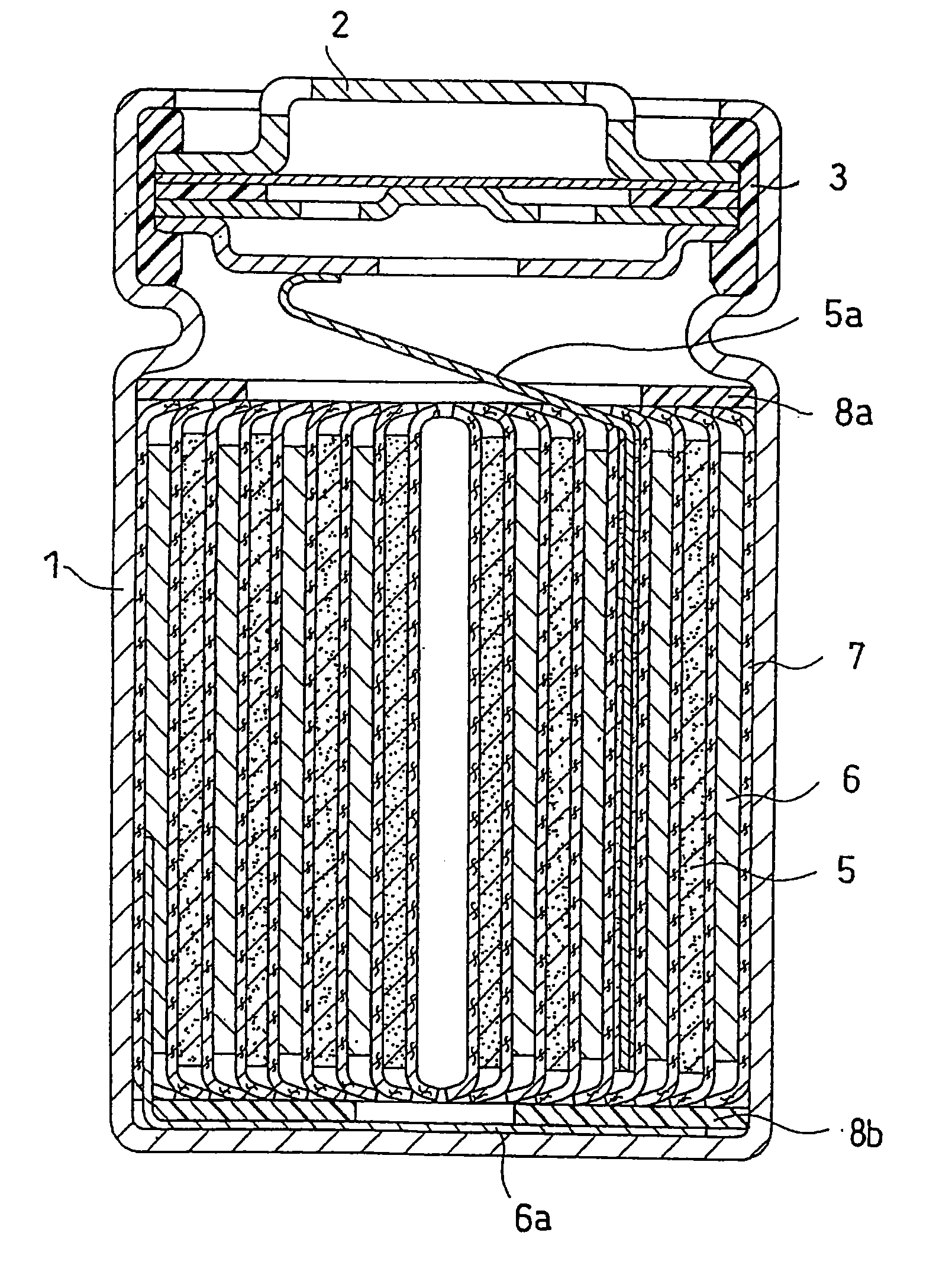
[0052]An aluminum foil serving as a current collector was rolled by three types of embossed rollers having different irregularities to form recessed portions on both surfaces of the aluminum foil. The rollers had a diameter of 150 mm, and the roller surfaces were embossed using a YAG laser (ML-2650B) available from Miyachi Corporation. Using three current collectors thus produced, three positive electrodes were produced in the same manner as in Example 1, except that the current collectors were not subjected to the softening process. Then, three lithium ion secondary batteries were produced in the same manner.


PUM


Abstract

An object of the present invention is to provide an electrode for a lithium ion secondary battery that can ensure a high level of safety even when exposed to severe conditions such as a nail penetration test or crush test, and exhibit excellent output characteristics.
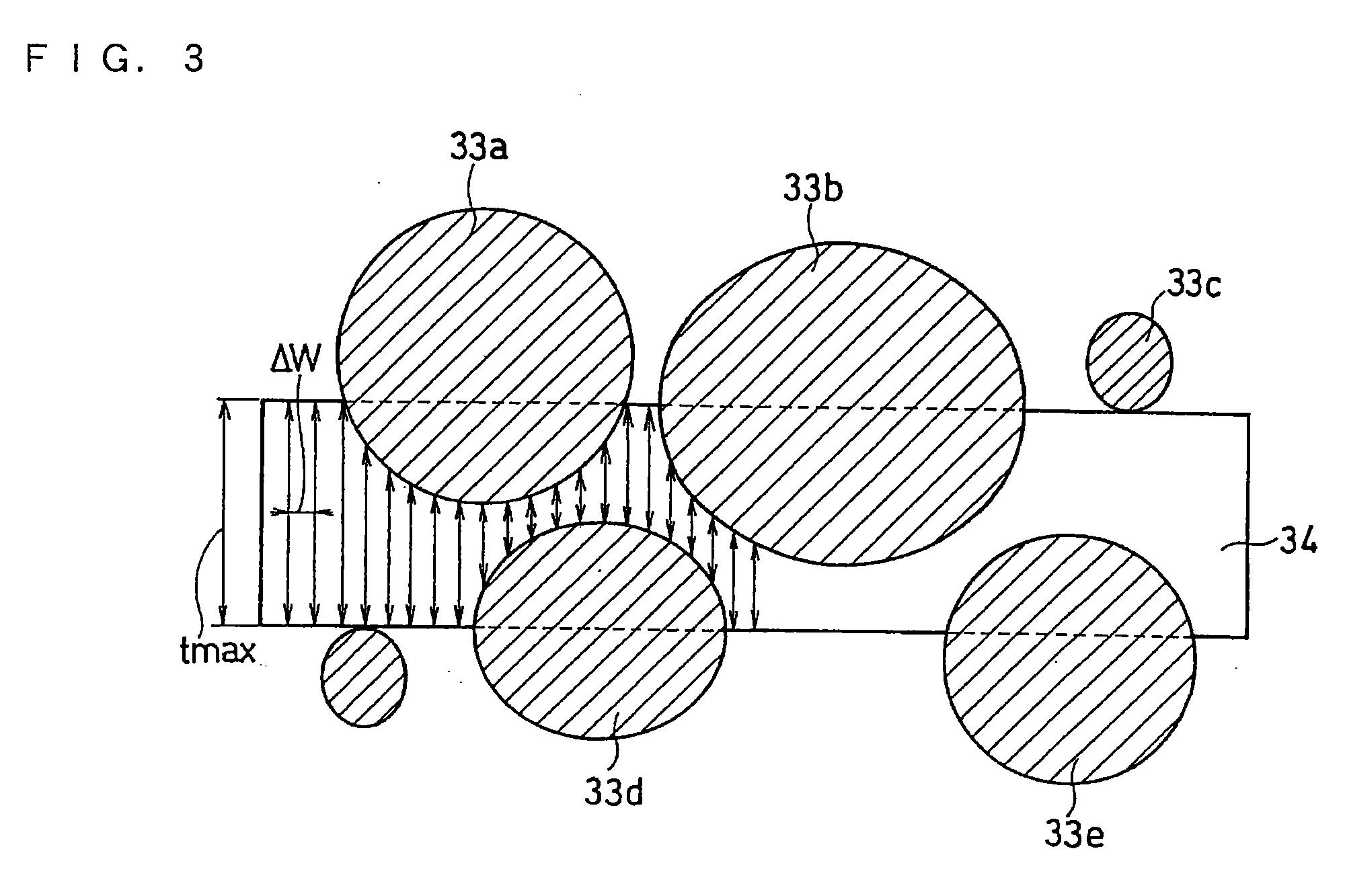
The present invention relates to an electrode for a lithium ion secondary battery having a material mixture containing active material particles capable of reversibly absorbing and desorbing lithium, and a current collector that carries the material mixture, wherein a surface of the current collector has recessed portions, and an area occupied by the recessed portions accounts for not less than 30% of an a material mixture carrying area of the current collector. The present invention further relates to an electrode for a lithium ion secondary battery wherein, in a cut surface obtained by simultaneously cutting a material mixture and a current collector vertically to an electrode plane, the maximum depth of recessed portions is not less than 1 μm, or a difference between an average thickness of a current collector and a maximum thickness of the current collector is not less than 0.35 μm.

Description

TECHNICAL FIELD[0001]The present invention relates to an electrode for a lithium ion secondary battery suitable for achieving both safety and output characteristics of a lithium ion secondary battery.BACKGROUND ART[0002]Lithium ion secondary batteries, which have features such as high output, high energy density and light weight, are employed in various applications, and studies of such batteries are still vigorously being conducted. Lithium ion secondary batteries include a non-aqueous electrolyte containing a non-aqueous solvent, and electrodes having a high energy density. Accordingly, a further improvement in safety has been an important issue for lithium ion secondary batteries.[0003]In order to insure a high level of safety, it is necessary to suppress an increase in battery temperature or the like in battery tests performed under extremely severe conditions such as a nail penetration test and a crush test. In the tests, if a material mixture is detached from a current collect...

Claims


Application Information

Patent Timeline
IPC IPC(8): H01M4/58H01M10/0525H01M10/36
CPCH01M4/70Y02T10/7011Y02E60/122H01M10/0525Y02E60/10H01M4/02H01M4/58H01M10/05Y02T10/70
Inventor NISHINO, HAJIMETSUTSUMI, SHUJIKASAMATSU, SHINJITAKEZAWA, HIDEHARUSHIMADA, MIKINARI
Owner PANASONIC CORP
Why Eureka
Try Eureka