Stabilizing mechanism for output torque of a transmission member

a technology of transmission member and stabilizer, which is applied in the direction of screwdrivers, slip couplings, wrenches, etc., can solve the problems of unstable output torque, unsuitable working fields necessitating stable torque, and both the above conventional techniques apparently lack the stabilizing/controlling system for output torque, etc., to achieve the effect of restricting output torque and stabilizing for

Active Publication Date: 2009-04-23
CHUANG CHIA CHIUNG
View PDF23 Cites 4 Cited by
  • Summary
  • Abstract
  • Description
  • Claims
  • Application Information

AI Technical Summary

Benefits of technology

[0004]It is therefore a primary object of the present invention to provide a stabilizing mechanism for output torque of a transmission member. The stabilizing mechanism serves to stabilize the force transmitted by the transmission member and restrict the output torque within a certain range.

Problems solved by technology

It is found by this applicant that both the above conventional techniques apparently lack stabilizing / controlling system for the output torque.
Accordingly, the output torque is unstable.
This is unsuitable for those working fields necessitating stable torque.
However, only when the application force exceeds the nominal transmitted torque, the engagement structure of the transmission shaft will jump aside to interrupt the transmission of torque.
This is not helpful in stabilizing the output torque.
That is, the value of the output torque under the nominal transmitted torque value is still unstable.

Method used


Image

  • Stabilizing mechanism for output torque of a transmission member
  • Stabilizing mechanism for output torque of a transmission member
  • Stabilizing mechanism for output torque of a transmission member

Examples


Embodiment Construction

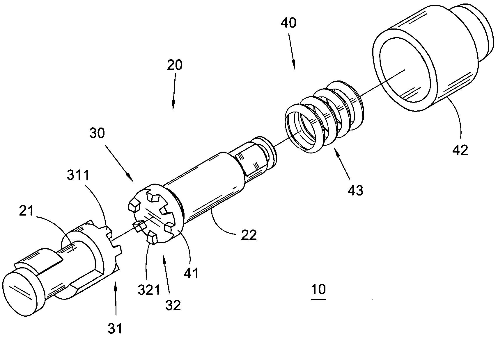
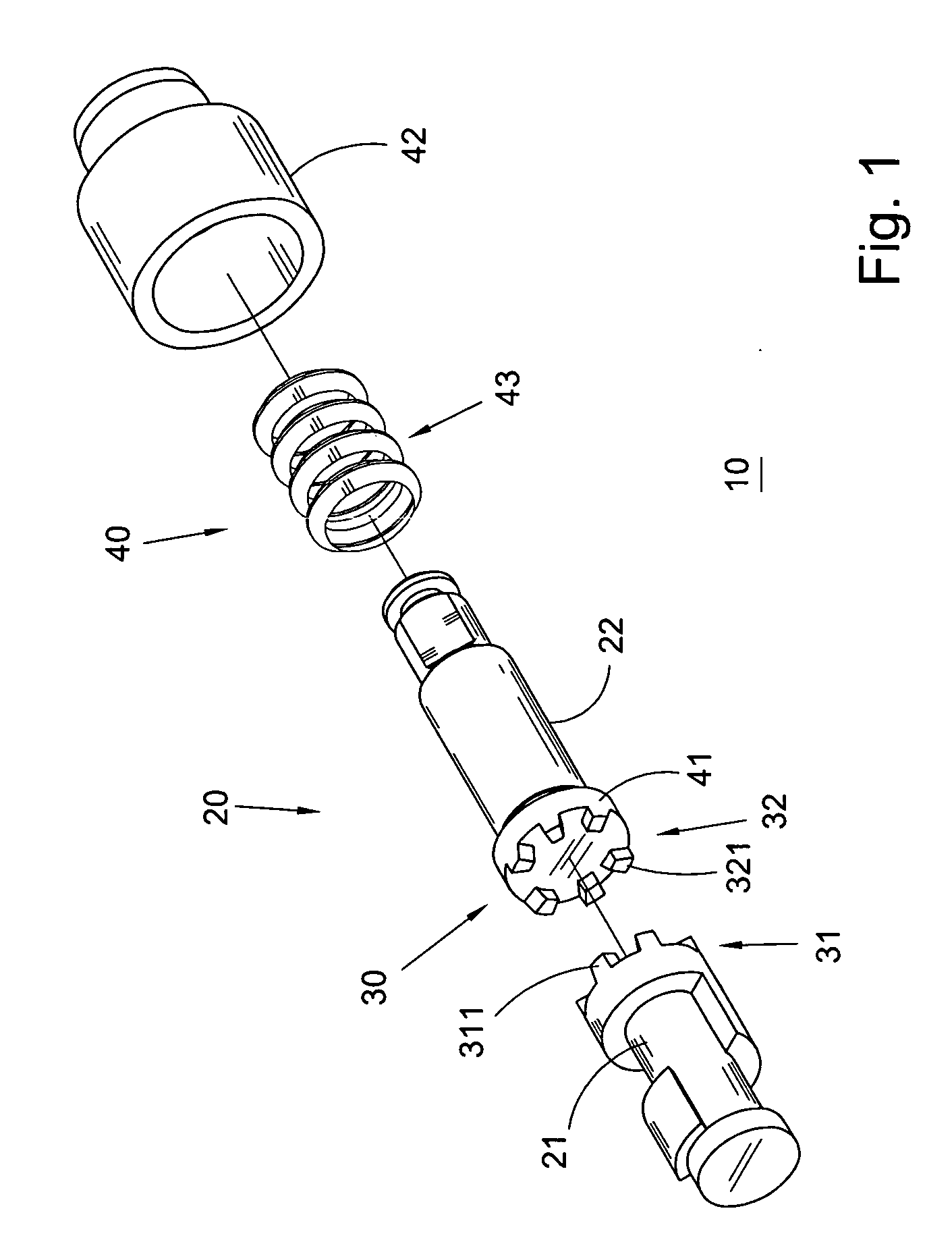
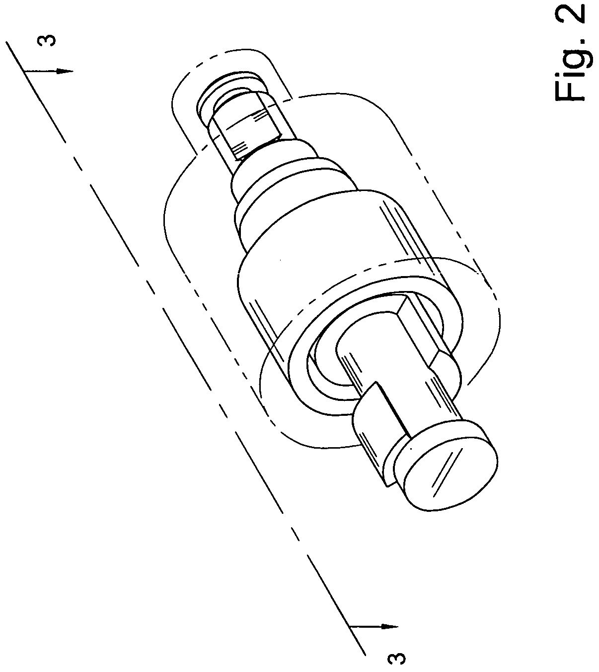
[0016]Please refer to FIGS. 1 to 4. The first embodiment of the stabilizing mechanism 10 for output torque of the transmission member of the present invention includes a transmission member 20, an engaging member 30 and a resilient member 40.

[0017]The transmission member 20 includes a force-input section 21 in form of cylindrical shaft and a force-output section 22 also in form of cylindrical shaft. The force-input section 21 and the force-output section 22 are concentrically arranged. One end of the force-input section 21 is opposite to one end of the force-output section 22. In general, the transmission member 21 is used in the same way as the conventional output shaft. In other words, the other end of the force-input section 21 is hammered by a hammering mechanism to rotate the force-input section 21. However, the force-output section 22 is quite different from the conventional one-piece output shaft. The force-input section 21 and the force-output section 22 are separable from e...


PUM


Abstract

A stabilizing mechanism for output torque of a transmission member, including: a transmission member having a force-input section and a force-output section which are separated from each other; an engaging member positioned between the force-input section and the force-output section, the engaging member including a first engaging section and a second engaging section respectively disposed on the force-input section and the force-output section in predetermined positions, the first and second engaging sections being engaged with each other by a predetermined engagement depth for transmitting force from the force-input section to the force-output section; and a resilient member for providing resilient force to keep the first and second engaging sections engaged with each other. The resilient member is compressible under force. The resilient member has a compressible distance shorter than the engagement depth of the first and second engaging sections.

Description

BACKGROUND OF THE INVENTION[0001]The present invention is related to a transmission technique of tools, and more particularly to a stabilizing mechanism for output torque of a transmission member.[0002]It is known that high-pressure gas serves as the power source of some kinds of tools. For example, U.S. Pat. No. 6,024,180 discloses a pneumatic wrench having an output shaft. One end of the output shaft is drivable by an impact mechanism (such as double-hammer type and pin-clutch type) of the pneumatic wrench, whereby the output shaft can rotate and operate. The other end of the output shaft extends out of the housing of the pneumatic wrench for outputting power. In addition, U.S. Pat. No. 7,281,458 discloses a transmission shaft applicable to unspecific power or non-power tools. The transmission shaft is designed with torque-limiting protective effect.[0003]It is found by this applicant that both the above conventional techniques apparently lack stabilizing / controlling system for th...

Claims


Application Information

Patent Timeline
Patent Type & Authority Applications(United States)
IPC IPC(8): F16D7/00
CPCF16D7/044
Inventor CHUANG, CHIA-CHIUNG
Owner CHUANG CHIA CHIUNG
Why Eureka
Try Eureka