Impeller for turbine

a technology for turbines and impellers, which is applied in the direction of machines/engines, mechanical equipment, liquid fuel engines, etc., can solve the problems of difficult to provide impellers at a low cost, difficult to efficiently convert the impulsive force of working gas into rotational force, and high cost of the impellers manufactured in this way

Inactive Publication Date: 2011-10-20
MAKE-UP ART COSMETICS
View PDF3 Cites 3 Cited by
  • Summary
  • Abstract
  • Description
  • Claims
  • Application Information

AI Technical Summary

Benefits of technology

[0024]Also, according to the fifth aspect of the present invention, since the inner circumferential edge of the basal portion of one type of disk blade has a larger diameter than the inner circumferential edge of the other type of disk blade or the inner circumferential edge of the basal portion of the other type of disk blade has a larger diameter than the inner circumferential edge of one type of disk blade, the inner circumferential edge portion of the basal portion of one type of disk blade is not present in a space portion between the inner circumferential edges of the basal portions of the other type of adjacent disk blades or the inner circumferential edge portion of the basal portion of the other type of disk blade is not present in a space portion between the inner circumferential edges of the basal portions of one type of adjacent disk blades, such that passage resistance of the working gas in the space portion is reduced, whereby loss of rotational energy which is imparted to the impeller for a turbine by the working gas can be reduced...

Problems solved by technology

However, in the related art of the impeller for a turbine (as above-described, for example), in order to form each of a number of blades (vanes) into a complicated three-dimensional curved shape, which is required to apply many working processes, and an impeller for a turbine manufactured in this way becomes significantly high in cost, such that ...

Method used


Image

  • Impeller for turbine
  • Impeller for turbine
  • Impeller for turbine

Examples


example

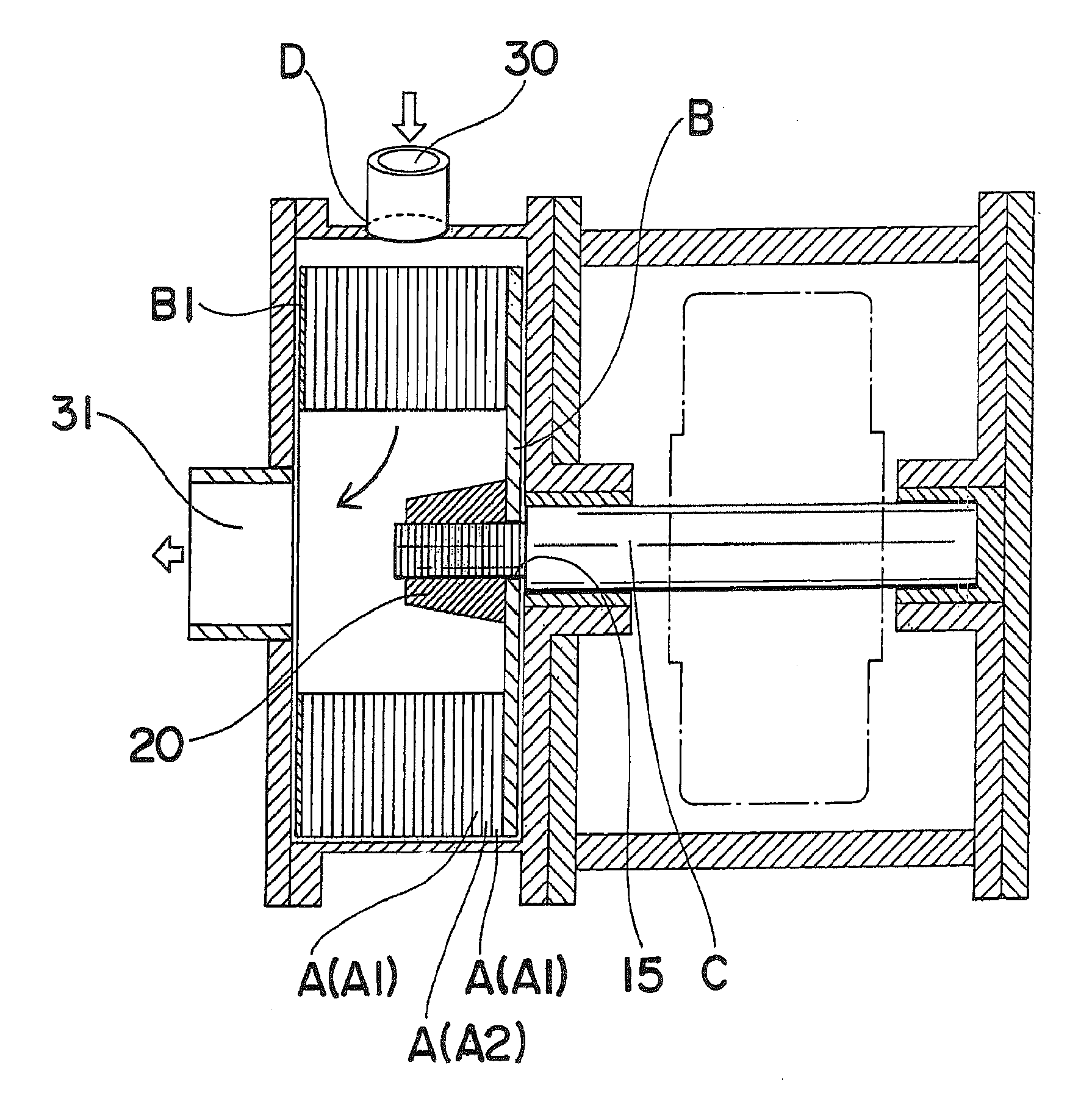
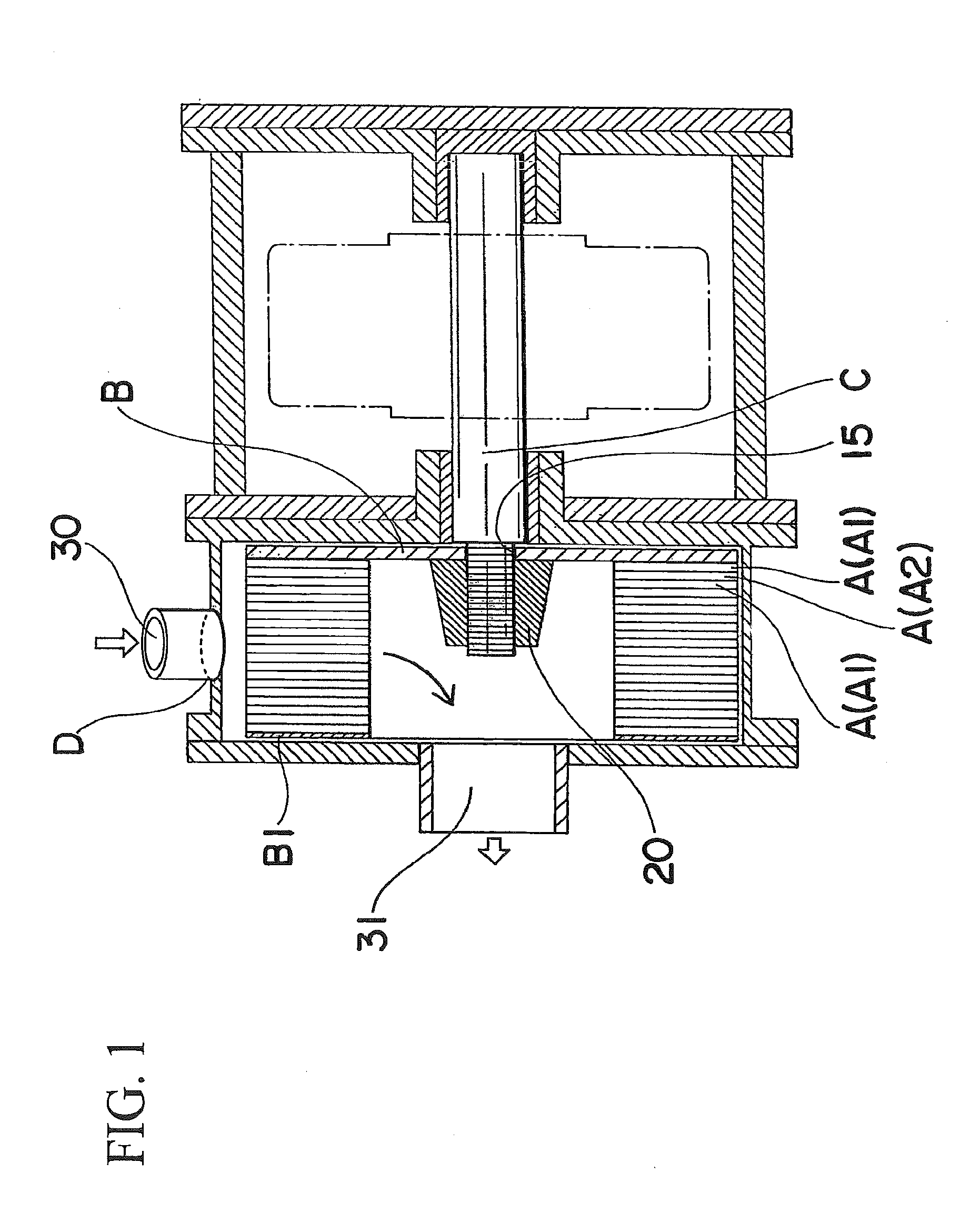
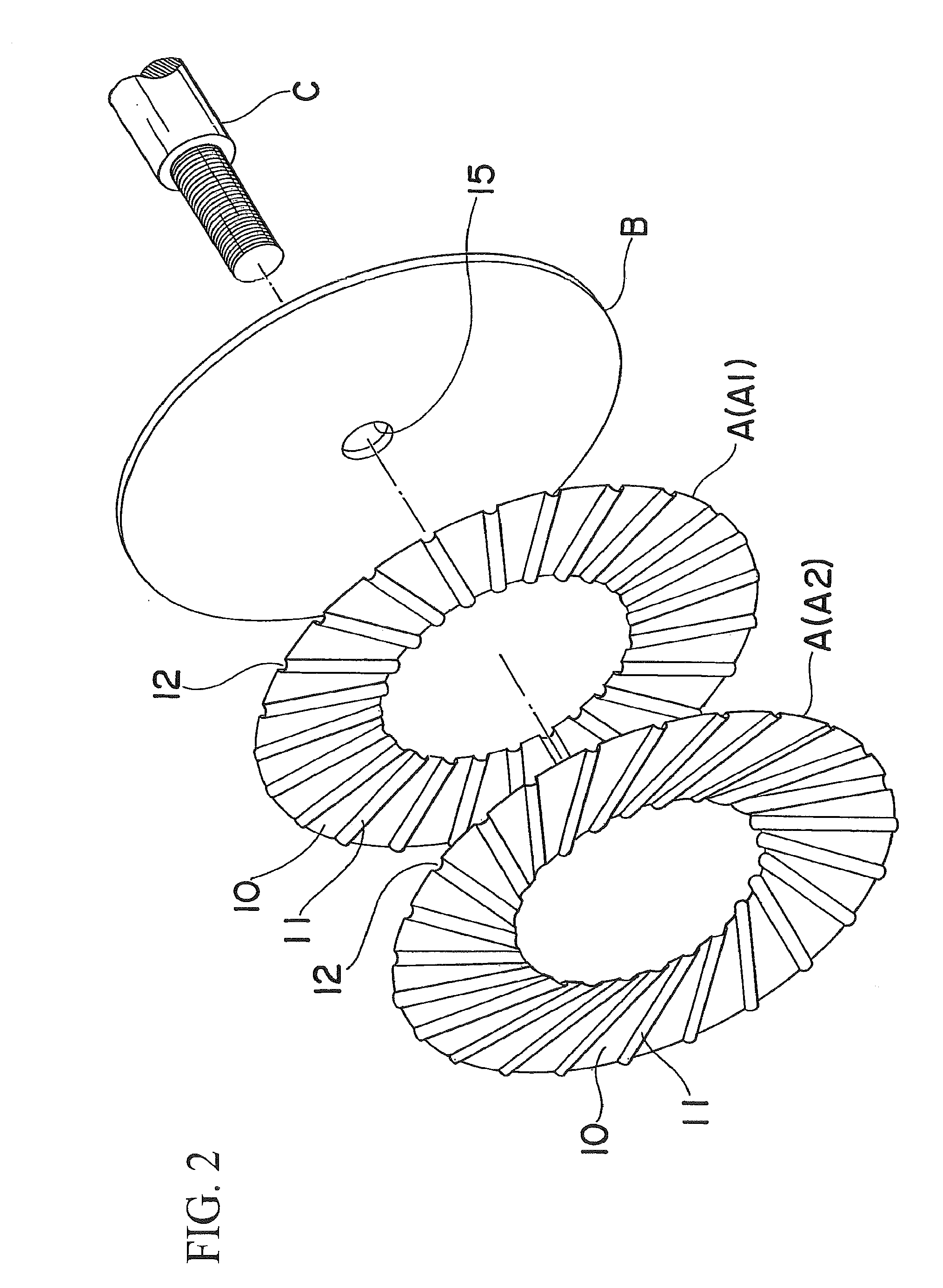
[0050]The disk blade A which is used in the impeller for a turbine is constituted by, for example, a metallic (for example, stainless steel) disk having a relatively thin annular disk shape and excellent corrosion resistance. Further, the disk blade is configured such that a number of pressed vane portions 11 are provided at the disk by a single (or, a plurality is also acceptable) press working and also a number of pressed vane portions 11 project from one surface side of the disk. Furthermore, the pressed vane portions 11 are formed from the inner circumferential edge to the outer circumferential edge of the disk. Also, a portion of the disk, in which the pressed vane portions 11 are not formed by the press working, becomes the basal portion 10, the inside of the projected pressed vane portion 11 becomes the recessed space 12, and the most protruded ridge portion of the pressed vane portion 11 becomes the projecting rear portion 11a.

[0051]Further, two or more types of disk blades...


PUM


Abstract

An impeller for a turbine includes an impeller body formed by alternately stacking and fixing two or more types of disk blades, a base plate, and a rotating shaft. A plurality of pressed vane sections projecting from one surface are formed on the base plate of each disk blade, and recessed spaces are formed in the pressed vane sections, respectively. The projecting rear sections of the pressed vane sections are affixed to the other surface of the base plate of the adjacent disk blade, and disposed in the recessed spaces of the pressed vane sections of the adjacent disk blade in the mutually crossing direction. A part of a working gas is moved in the recessed spaces, and moved forward in the rotating direction over the projecting rear sections.

Description

TECHNICAL FIELD[0001]The present invention mainly relates to an impeller for a turbine, which is built to be freely rotatable in a casing and is rotated by an impulsive force of an expanded suitable working gas (for example, Freon gas or the like that is a heat medium) which is ejected from an inlet of the casing at high speed, being received by a plurality of vane portions, and drives a power generator or the like by using the rotational force, and in particular, to an impeller for a turbine, which is devised so as to be able to generate a well-balanced and stable rotational force by efficiently using an impulsive force of the working gas, to be able to be easily manufactured in a simple configuration, to be able to be configured to be small, light weight, and compact, to be suitable for mass production, to significantly reduce costs, to be excellent in versatility, and to be economical.BACKGROUND ART[0002]In the past, as this type of impeller for a turbine, various impellers for t...

Claims


Application Information

Patent Timeline
IPC IPC(8): F01D5/02
CPCF01D1/22F01D1/34F01D5/048F01D15/005F05D2250/182F04D29/281F05D2220/60F05D2230/237F04D29/023Y02T50/60F01D1/06F01D1/08F01D5/04F01D5/14
Inventor MATSUSHITA, HIROAKI
Owner MAKE-UP ART COSMETICS
Why Eureka
Try Eureka