Mechanical sealing device for sanitary pump

A technology of mechanical sealing device and sanitary pump, applied in mechanical equipment, components of pumping device for elastic fluid, pump, etc., can solve problems such as inability to always press fit, blocking spring, poor reliability, etc.

Active Publication Date: 2013-06-12
NINGBO VULCAN TECH CO LTD
View PDF6 Cites 4 Cited by
  • Summary
  • Abstract
  • Description
  • Claims
  • Application Information

AI Technical Summary

Problems solved by technology

[0003] The above prior art mechanical seals for sanitary pumps have the following disadvantages: since the spring is installed in the flushing hole of the static ring seat, after the medium enters the flushing hole of the static ring seat, it is very easy to cause the spring to be blocked, so that the static ring cannot Under the action of the spring, the axial direction is automatically compensated, that is, the end face of the static ring cannot always be press-fitted to the end face of the moving ring, so the reliability is poor, resulting in the failure of the entire mechanical seal device
[0004] At present, a single-piece wave spring is also used to replace the coil spring, but when installing this way, an opening or a through hole must be opened on the wave spring for the bolt to pass through, which reduces the stability of the spring, and the single-piece wave spring still has a certain degree of If the flushing hole on the static ring is blocked, it may cause the mechanical seal to fail.

Method used


Image

  • Mechanical sealing device for sanitary pump
  • Mechanical sealing device for sanitary pump
  • Mechanical sealing device for sanitary pump

Examples


Embodiment Construction

[0016] The present invention will be further described below in conjunction with accompanying drawing.

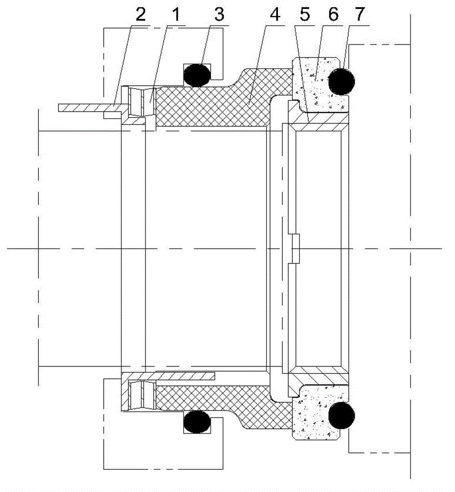
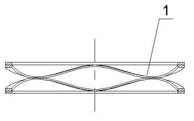
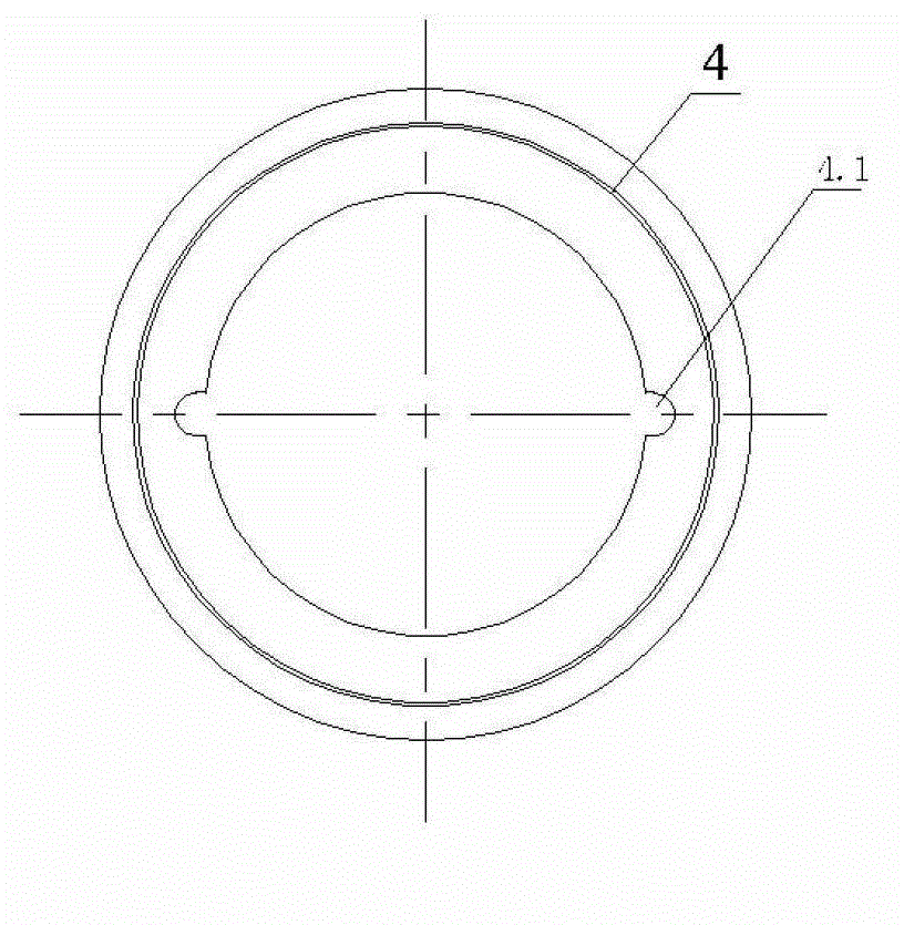
[0017] Such as figure 1 , figure 2 , image 3 , Figure 4 , Figure 5 , Image 6 As shown, a mechanical seal device for a sanitary pump of the present invention includes a moving ring seat 5 that is rotated with a rotating shaft, a moving ring 6 that is tightly fitted outside the moving ring seat 5 and pressed tightly with the impeller, a static ring seat 2, a set The static ring 4 outside the rotating shaft, the end face of the static ring 4 is press fit on the end face of the moving ring 5; there is a gap between the inner hole wall of the static ring 4 and the rotating shaft; it also includes a winding wave spring 1, that is, the wave spring 1 is composed of thin sheets composed of multiple crests and troughs. One end of the static ring seat 2 is limited in the circumferential direction of the pump cover, and the other end is limited in the circumferential directio...


PUM


Abstract

The invention discloses a mechanical sealing device for a sanitary pump. The mechanical sealing device comprises a moving ring seat (5), a moving ring (6), a stationary ring seat (2) and a stationary ring (4), wherein the moving ring seat (5) is screwed with a rotary shaft, the moving ring (6) is closely fitted outside the moving ring seat (5) and is tightly pressed on an impeller, and the stationary ring (4) is arranged outside the rotary shaft. The end face of the stationary ring (4) is pressed and fitted on the end face of the moving ring (6), and a gap is formed between the inner hole wall of the stationary ring (4) and the rotary shaft. The mechanical sealing device is characterized by also comprising a twined wave spring (1). One end of the stationary ring seat (2) is circumferentially limited with a pump cover, and the other end of the stationary ring seat (2) is circumferentially limited with the stationary ring (4). One end of the wave spring (1) is abutted against the end face of the stationary ring (4), and the other end of the wave spring (1) is abutted against the step surface of the stationary ring seat (2). The stationary ring of the mechanical sealing device for the sanitary pump can axially automatically compensate under the effect of the spring so as to ensure that the end face of the stationary ring is always pressed and fitted onto the end face of the moving ring and prevent the whole mechanical sealing device from losing efficacy.

Description

technical field [0001] The invention relates to a mechanical sealing device, in particular to a mechanical sealing device for a sanitary pump. Background technique [0002] Since the mechanical seals used in sanitary pumps have high requirements on hygiene, it is not only required to seal the liquid medium, but also to ensure that the dust is not easy to enter, so as to ensure the hygiene and safety of food. Sanitary pumps are equipped with a mechanical seal device, which includes a moving ring seat that rotates with the rotating shaft and is tightly pressed with the impeller, a moving ring that is tightly fitted outside the moving ring seat, and a static ring seat that is limited in the circumferential direction of the pump cover. The static ring and the spring tightly matched with the static ring seat, the end face of the static ring is press fit on the end face of the moving ring; the spring is embedded in the through hole on the side wall of the static ring seat, and one...

Claims


Application Information

Patent Timeline
Patent Type & Authority Applications(China)
IPC IPC(8): F04D29/12
Inventor 邬国平谢方民颜碧能
Owner NINGBO VULCAN TECH CO LTD
Why Eureka
Try Eureka