Steering column assembly

a technology of steering column and assembly, which is applied in the direction of vehicle sub-unit features, mechanical control devices, instruments, etc., can solve problems such as poor operability, and achieve the effects of reducing clamping torque, small operation force, and reducing operation for

Active Publication Date: 2009-04-30
FUJI KIKO CO LTD
View PDF2 Cites 10 Cited by
  • Summary
  • Abstract
  • Description
  • Claims
  • Application Information

AI Technical Summary

Benefits of technology

[0012]In the steering column assembly according to any one of the first and second aspects of the present invention, when the operation lever is rotated from an unlock position to a lock position, the eccentric cam is rotated in a lock direction by the clamp bolt. Thereby, the radial dimension of the eccentric cam progressively increases in its circumferential direction. Thus, the eccentric cam presses the inner tube against the outer tube with a ring. Hence, the inner tube is pressure-contacted to and engaged with the outer tube. Finally, the inner tube is locked. Additionally, when the operation lever is rotated from the lock position to the unlock position, the cam body is rotated in an unlock direction by the clamp bolt. Thereby, the radial dimension of the eccentric cam progressively decreases in its circumferential direction. Thus, the ring is detached from the inner tube. Hence, the inner tube is released from the locked condition in which the inner tube is being pressure-contacted to and engaged with the outer tube. This makes it possible for the outer tube to be telescopically adjusted (to be slid in the axial direction) relative to the inner tube by use of a small operation force.
[0013]The eccentric cam is pressure-contacted to and engaged with the inner tube with the ring fitted on the outer periphery of the eccentric cam. This arrangement enables the radial dimension of the eccentric cam to make smaller. Accordingly, it is possible to reduce a clamping torque which needs to be applied to the clamp bolt when the outer peripheral surface of the ring is pressed against the inner tube by rotating the eccentric cam to lock the inner tube. For this reason, this embodiment is capable of reducing the operation force needed to be applied to the operation lever, and accordingly of enhancing the operability.
[0014]In addition, when a force is applied to the steering column tube in a direction in which the steering column tube contacts while the inner tube is being locked to the outer tube by pressing the outer peripheral surface of the ring against the inner tube, the ring is biased in an unlock direction by a friction force through the inner tube, and thus the ring rotates. However, it is possible to prevent the eccentric cam from rotating in the unlock direction because the ring slips on the eccentric cam. For this reason, the inner tube can be kept being locked to the outer tube firmly. Moreover, the radial dimension of the eccentric cam is smaller than that of an eccentric cam which does not provide with a ring. This decreases a torque for driving the eccentric cam in the unlock direction when the eccentric cam is biased in the unlock direction with the ring. In this respect, it is possible to prevent the eccentric cam from rotating in the unlock direction.

Problems solved by technology

However, the technique disclosed in Japanese Patent No. 3783524 has a problem of poor operability for the following reason.

Method used


Image

  • Steering column assembly
  • Steering column assembly
  • Steering column assembly

Examples


Embodiment Construction

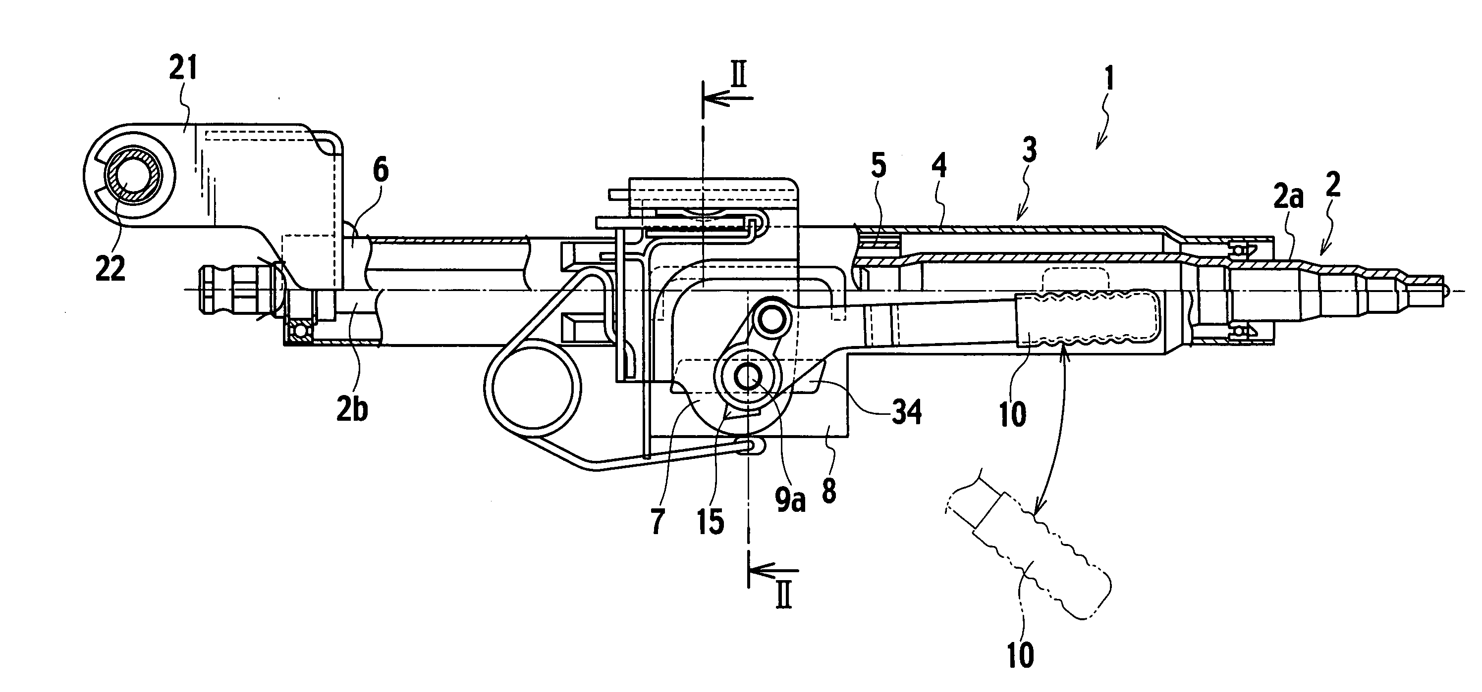
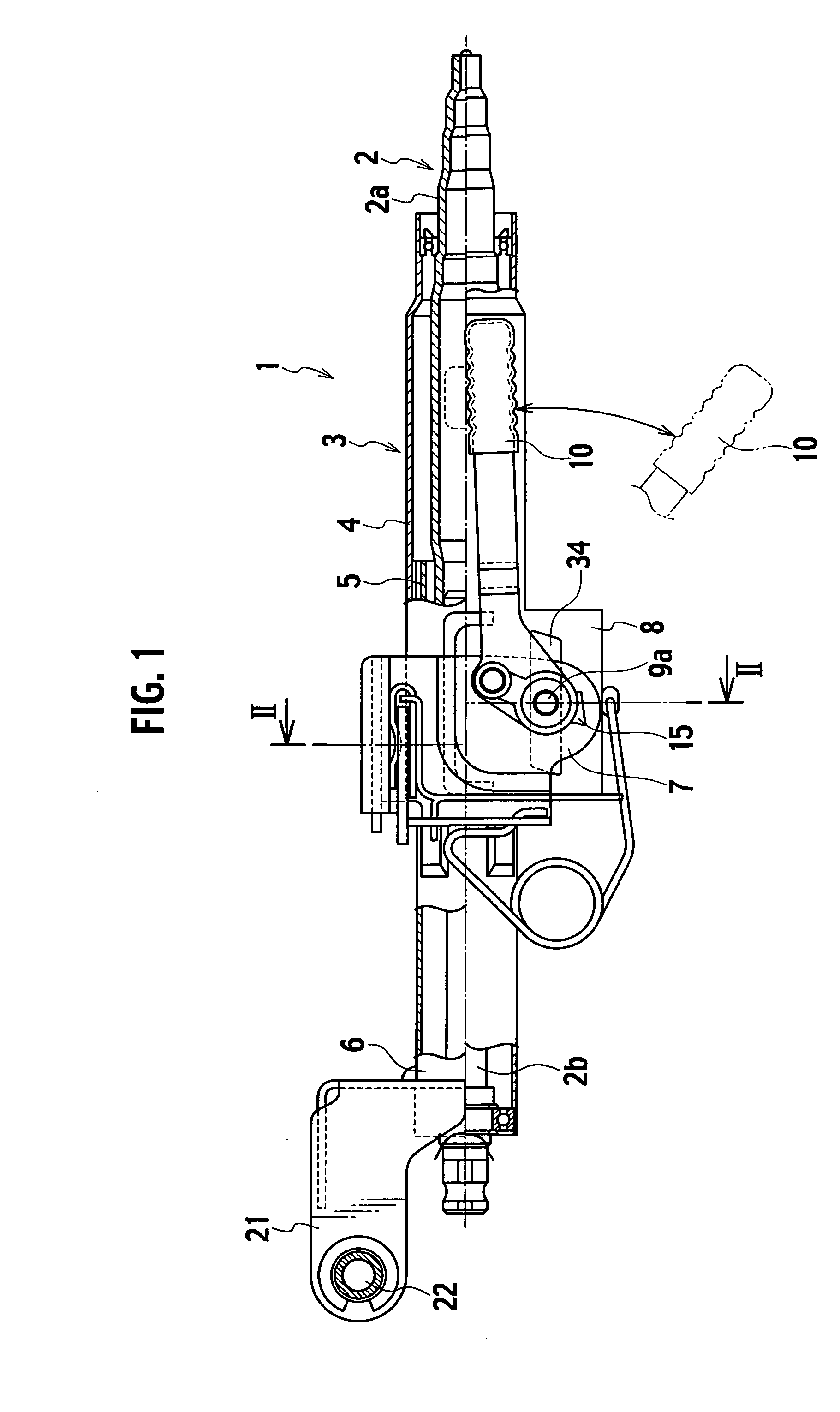
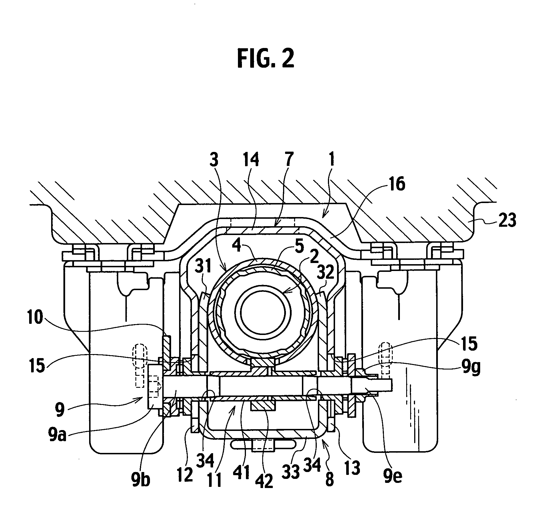
[0031]Descriptions will be provided hereinbelow for the embodiment of the present invention by referring to the drawings. FIG. 1 is a front view of a steering column assembly according to an embodiment of the present invention. FIG. 2 is an auxiliary cross-sectional view of FIG. 1 taken along the line II-II. FIGS. 3A and 3B are axial cross-sectional views schematically showing a chief part of the steering column assembly. FIG. 3A is the cross-sectional view showing the steering column assembly being locked. FIG. 3B is the cross-sectional view showing the steering column assembly being released from locking. FIG. 4 is a perspective assembly drawing of a cam body consisted of an eccentric cam and a ring. FIG. 5 is a front view of the cam body. FIG. 6 is an auxiliary cross-sectional view of FIG. 5 taken along the VI-VI line. FIG. 7 is a plan view of the cam body. FIG. 8 is a plan view showing how the eccentric cam with the ring being detached therefrom. FIG. 9 is a perspective view sho...


PUM


Abstract

The steering column assembly includes: an upper clamp 7; a distance bracket 8 fixed to an outer tube 4; a clamp bolt 9 including a shank 9b inserted in tilt long holes formed in the upper clamp 7 and telescopic long holes formed in the distance bracket 8; an operation lever 10 configured to rotate integrally with the bolt 9; a cam body 11 configured of an eccentric cam 41 and a ring 42, the eccentric cam 41 being provided on the shank 9b, the radial dimension of the eccentric cam 41 gradually changing in its circumferential direction, and the ring 42 rotatably fitted on the outer periphery of the eccentric cam 41. The cam body 11 rotates and is pressed against an inner tube 5 to lock the inner tube 5 to an outer tube 4.

Description

BACKGROUND OF THE INVENTION[0001]1. Field of the Invention[0002]The present invention relates to a steering column assembly including a telescopic adjustment mechanism which allows a driver to adjust the position of a steering wheel depending on the driver's physique and preference in order that the driver can feel comfortable while driving.[0003]2. Description of the Related Art[0004]Known is a steering column assembly including a tilt adjustment mechanism and a so-called telescopic adjustment mechanism. The tilt adjustment mechanism allows a driver to adjust the height of the steering wheel depending on the driver's physique and driving posture. The telescopic adjustment mechanism allows the driver to adjust the front-back position of the steering wheel in the axial direction of the steering shaft depending on the driver's physique and driving posture.[0005]In general, when a telescopic adjustment is applied to the steering wheel, the steering column assembly of this type causes a...

Claims


Application Information

Patent Timeline
Patent Type & Authority Applications(United States)
IPC IPC(8): B62D1/18B62D1/185B62D1/184
CPCY10T74/20636B62D1/184B62D1/12B62D1/187B60Y2410/102
Inventor UESAKA, YOTA
Owner FUJI KIKO CO LTD
Why Eureka
Try Eureka