Ratcheting serpentine belt tool

a serpentine belt and tool technology, applied in the field of serpentine belts, can solve the problems of difficult to use the tool in an efficient manner in restricted spaces, restricted movement, and difficulty in efficient use of the tool in restricted spaces, and achieve the effect of convenient use and efficient us

Inactive Publication Date: 2009-04-30
LISLE CORPORATION
View PDF27 Cites 8 Cited by
  • Summary
  • Abstract
  • Description
  • Claims
  • Application Information

AI Technical Summary

Benefits of technology

[0007]One of the benefits of the construction or tool of the invention is the ability to place the reversible pawl in a neutral, non-engaged position. As a consequence, the ratchet wheel and socket may be appropriately positioned and oriented with respect to the elongate handle within the engine compartment of a vehicle. Then, the reversible pawl may be positioned in a clockwise or counterclockwise driving position. This enables efficient positioning or orientation of the handle in the engine compartment and thus facilitates the ability to use the tool in an effective manner.
[0009]Another object of the invention is to provide a simple, yet rugged, economical, easy to use and efficient tool which may be utilized to release pulley tension on a serpentine belt of a vehicle engine.

Problems solved by technology

Despite such advances in the design of serpentine belt tools, problems remained with respect to their utilization.
For example, utilizing the tool in an efficient manner in restricted spaces is often difficult.
Such movement may be restricted because of the configuration of the engine compartment for example.

Method used


Image

  • Ratcheting serpentine belt tool
  • Ratcheting serpentine belt tool
  • Ratcheting serpentine belt tool

Examples


Embodiment Construction

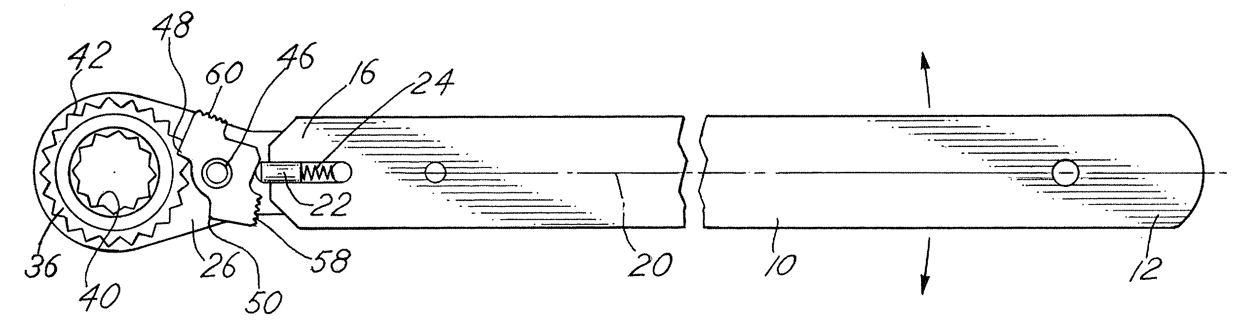
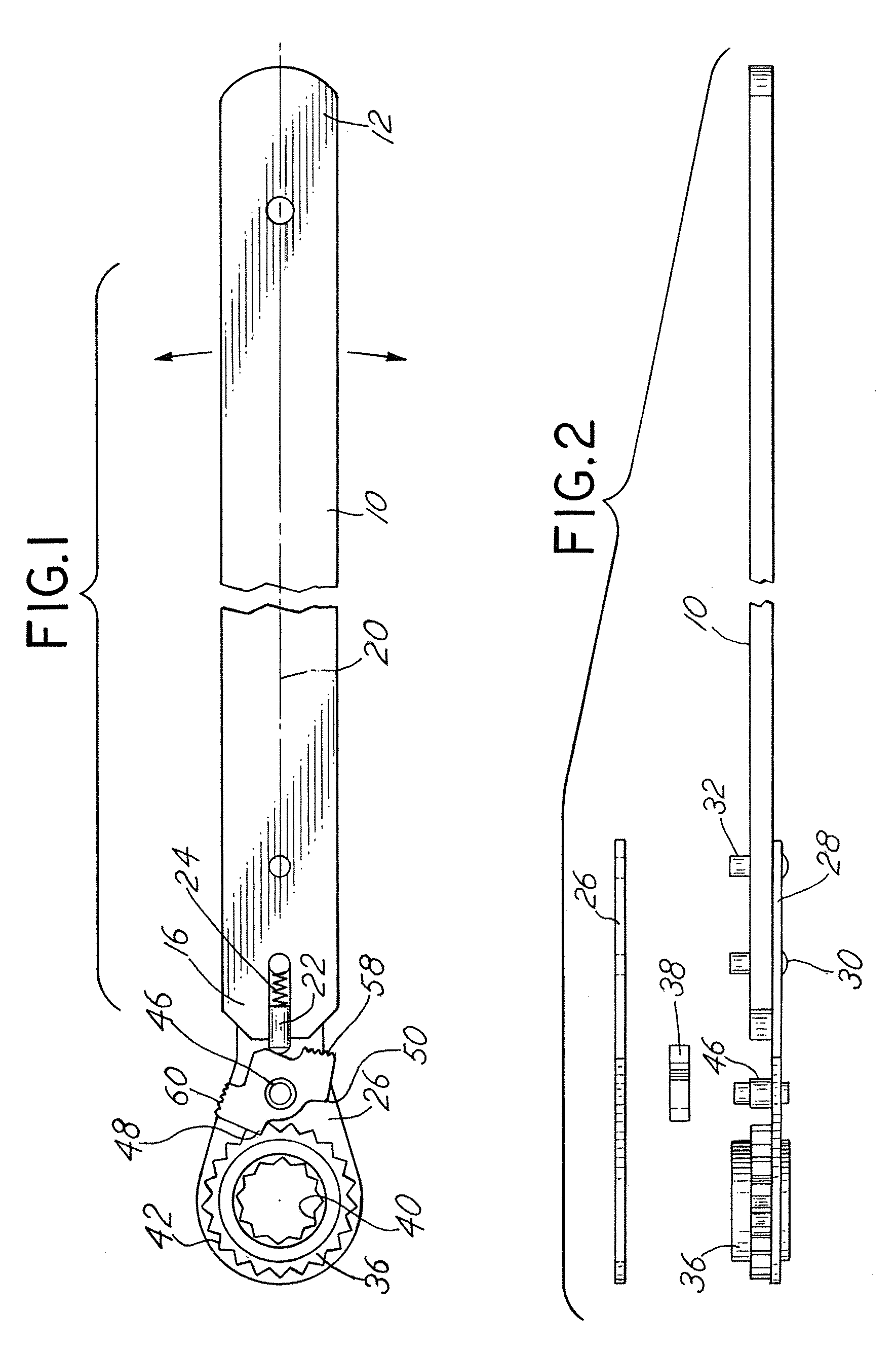
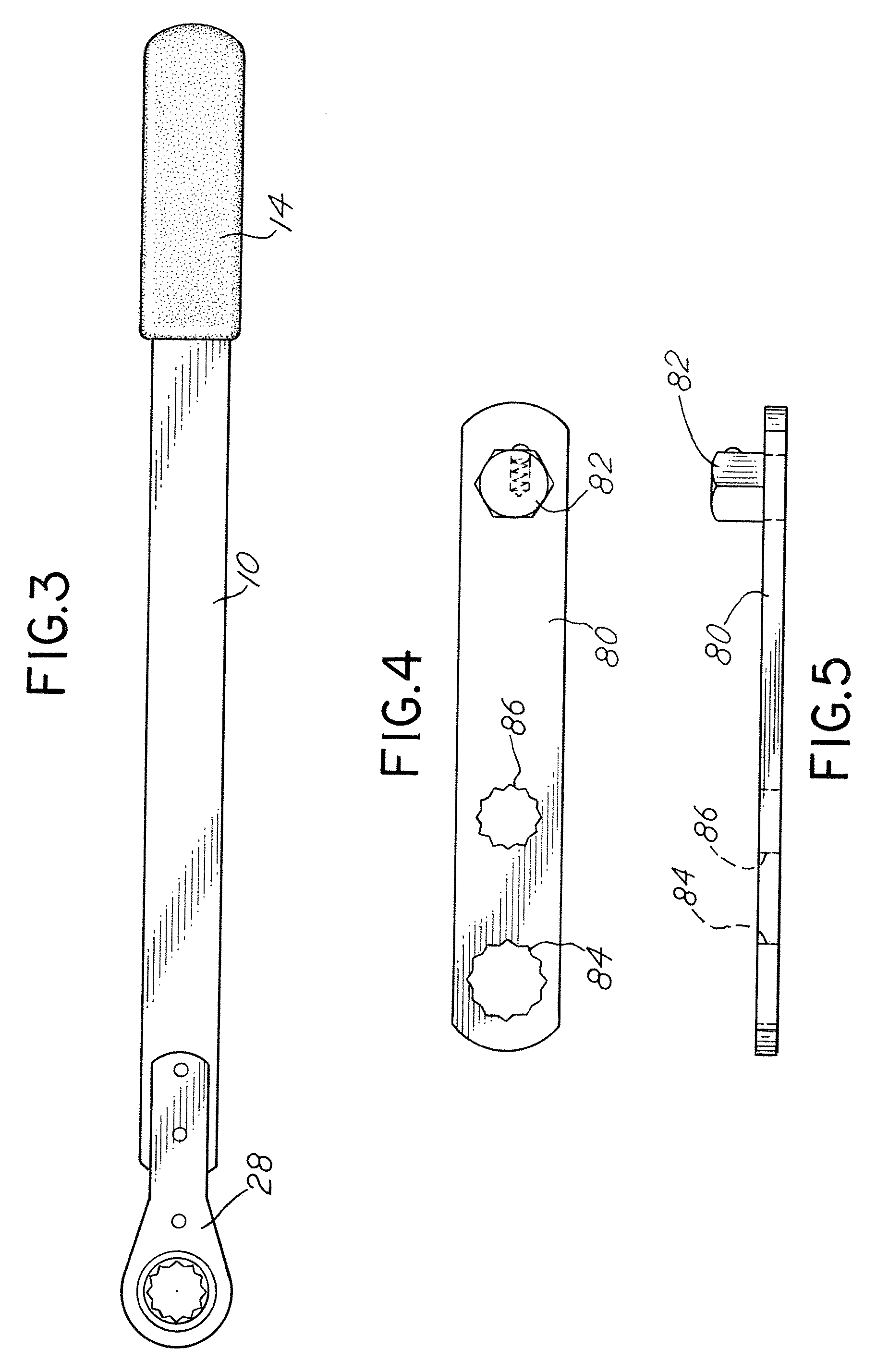
[0021]The tool of the invention, in the embodiment depicted, includes an elongate actuation handle 10 having a manual grip end 12 with a foam grip material 14 molded or fastened thereto. Typically, the handle 10 is in the range of 10 to 20 inches in length. The handle 10 is in the form of a flat plate with a drive end 16 opposite the manual grip end 12. The drive end 16 includes an elongate slot 18 which extends longitudinally along a center line axis 20 of the handle 10. The elongate slot 18 includes a plunger pin 22 biased outwardly by a spring 24 along the longitudinal axis 20.

[0022]A first end cover plate 26 and a second end cover plate 28 are positioned on opposite sides of the handle 10 at the drive end 16 and are retained by solid rivets 30 and 32. The end plates 26 and 28 are thus held in position and constitute longitudinal extensions of the elongate actuator handle 10. The end plates 26, 28 retain a rotatably mounted ratchet wheel 36 and a reversible pawl 38 therebetween. ...


PUM


Abstract

A serpentine belt tool for releasing tension on a serpentine belt biased by an idler pulley includes an elongate handle which is connected to a ratchet mechanism. The pawl associated with the ratchet mechanism has three positions including a neutral position which facilitates placement of the tool on an idler pulley.

Description

BACKGROUND OF THE INVENTION[0001]In a principal aspect the present invention relates to a tool for use to control or adjust the tension of a serpentine belt, particularly a serpentine belt associated with an internal combustion vehicle engine.[0002]Modern diesel and internal combustion engines typically include closed loop flexible belts which have a serpentine shape inasmuch as they fit around and connect a plurality of pulleys associated with various operating components of the engine. Often a serpentine belt is tensioned by means of an idler pulley mounted at the end of a cantilever, spring loaded or spring biased arm. In seeking to repair or replace a component of an engine having a serpentine belt, it may be necessary to release the tension of the idler pulley on the belt.[0003]Various tools have been developed to effect release of the tension of the idler pulley including tools manufactured by applicant's assignee, Lisle Corporation and identified as Serpentine Belt Tools, Pro...

Claims


Application Information

Patent Timeline
Patent Type & Authority Applications(United States)
IPC IPC(8): B25B13/46
CPCB25B13/463B25B27/0035B25B25/00
Inventor PLOEGER, RANDALL J.
Owner LISLE CORPORATION
Why Eureka
Try Eureka